Top Flite TOPA0700 User Manual
Page 29
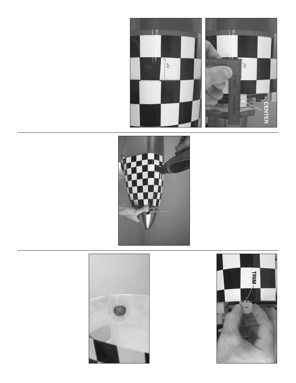
❏
4.
Mar
k the center of all f
our mounting b
loc
ks with
a pen.
La
y a small r
uler on the fuselage with one
edge o
v
er the mar
k.
Use a f
elt-tip pen to dr
a
w
a line
directly on the fuselage along the r
u
ler
.
Mar
k another
line on the fuselage 2-1/2" [65mm] as sho
wn from
the center mar
k on the mounting b
loc
k.
When the
co
wl is in place the lines and measurements will
pinpoint the center of the b
loc
ks under the co
wl.
❏
5.
Mar
k the remaining three co
wl mounting b
loc
ks
and the fuselage the same w
a
y.
❏
6.
Slide the co
wl o
v
er the engine onto the
fuselage
.
U
se a Dremel tool with a cutting bit to tr
im
the co
wl where necessar
y so y
ou can get it to fit o
v
er
the engine
.
At this stage the co
wl shouldn’t require
m
uch tr
imming since the carb
uretor and m
u
ffler ha
v
e
been remo
v
ed.
❏
7.
If necessar
y,
use a prop reamer or the
appropr
iate-siz
e dr
ill to enlarge the hole in the prop
fo
r the cr
ankshaft (or propeller bolt).
❏
8.
T
empor
ar
ily mount the spinner bac
kplate and
propeller to the engine
.
Mount the spinner cone to
the bac
kplate with the 3mm scre
ws
.
❏
9.
Use tape or ha
v
e
an assistant hold the co
wl in
position.
Be cer
tain to pro
vide clear
ance betw
een the
co
wl and spinner—1/8" to 3/16" [3 to 5mm] should be
adequate
.
Also be cer
tain the chec
k
ers on the top of
the co
wl are centered on the chec
k
ers on the top of
the fuselage
.
❏
10.
Mar
k the co
wl 2-1/2" [65mm] from the mar
k on
the line indicating the center of one of the co
wl
mounting b
loc
ks
.
D
rill a 3/32" [2.4mm] hole through
the co
wl into the mounting b
loc
k inside
.
❏
12.
T
empor
ar
ily f
asten the co
wl to that mounting
b
loc
k b
y
par
tially installing a #4 x 5/8" [16mm] scre
w
.
Dr
ill the rest of the holes the same w
a
y.
❏
13.
After all f
our holes ha
v
e
been dr
illed, remo
v
e
the co
wl and enlarge the holes
in the co
wl onl
y
with
a 1/8" [3.2mm] dr
ill.
Mount the co
wl with the scre
ws
.
❏
14.
Remo
v
e
the spinner
, prop and co
wl.
W
ipe the
alignment mar
ks from the fuselage using one of the
small paper to
w
el squares dampened with alcohol.
❏
15.
Dr
ill a 1/8" [3.2mm] hole through f
our of the
supplied 1/16" x 7/8" [1 x 22mm] round, plyw
ood
co
wl
reinf
or
cements
.
Align the hole in one of the
reinf
orcements o
ver the hole in one of the co
wl
mounting b
loc
ks as sho
wn in the photo
.
If necessar
y,
tr
im the aft edge of the co
wl reinf
orcement so it will not
interf
ere with the fuselage when glued inside the co
wl.
❏
16.
If necessar
y,
tr
im the remaining three co
wl
reinf
orcements the same w
a
y.
❏
17.
Roughen the inside of the co
wl around the scre
w
holes
.
Add a dab of petroleum jelly or a drop of
household oil to the threads of f
our 4-40 x 3/8" [9.5mm]
scre
ws and 4-40 n
u
ts
.
G
lue the co
wl reinf
orcements to
the inside of the co
wl using the scre
ws and n
u
ts to hold
them until the epo
xy hardens
.
❏
18.
After the epo
xy has hardened, remo
v
e
the
scre
ws
.
Redr
ill the holes with a 1/8" [3.2mm] dr
ill,
then mount the co
wl with f
our #4 x 5/8" [16mm]
scre
ws
, #4 flat w
ashers and #4 loc
k w
ashers
.
Mount
the spinner and prop to see ho
w it all looks
.
- 29
-