Top Flite TOPA0410 User Manual
Page 53
- 53 -
Most modern engines in the size range specified provided
more than ample power for the Corsair. It is recommended,
therefore, that you run the engine somewhat rich for the
first flights because the excess fuel running through the
engine provides a cooling effect. If your engine is not
broken in, run a few tanks of fuel through it on the ground
with the cowl removed before flying.
NON-FUNCTIONAL LANDING GEAR DOORS
❏ A template is provided on the plans for non-functional
landing gear doors. The doors are cut from 1/8" [3.2mm]
plywood (not included). The mounts are made from
hardwood blocks with a 1/2" [12.7mm] hole drilled through
the center of the block. A 1/16" [1.6mm] pilot hole is drilled
through the block along side the 1/2" [12.7mm] hole. The
blocks are then cut in half. One half of the block is glued to
the doors. In the other half of the blocks enlarge the pilot
holes to 3/32" [2.4mm]. Attach the doors to the landing
gear struts with #2 sheet metal screws. We recommend
that the Corsair not be flown with the landing gear doors
attached. The doors are for static appearance only.
SET THE CONTROL THROWS
FULL
THROTTLE
RUDDER
MOVES
RIGHT
ELEVATOR
MOVES DOWN
RIGHT AILERON
MOVES UP
LEFT AILERON
MOVES DOWN
4-CHANNEL RADIO SET UP
(STANDARD MODE 2)
The throws are measured at the widest part of the
elevators, rudder, ailerons and flaps. Adjust the position of
the pushrods at the servo horns to control the amount of
throw. You may also use the ATV’s if your transmitter has
them. Set the mechanical linkages so the ATV’s are near
100% for the best servo resolution (smoothest, most
proportional movement).
2-1/2"
[64 mm]
3/4"
[19 mm]
These are the recommended control surface throws:
ELEV
A
TOR
HIGH RATE
LOW RATE
Up and
Down
Up and
Down
Up and
Down
Down
1"
[25 mm]
Up and
Down
Down
3/4"
[19 mm]
13°
1-1/2"
[38 mm]
1-1/2"
[38 mm]
Right
& Left
Right
& Left
2-1/2"
[64 mm]
RUDDER
AILERONS
FLAPS
1/2"
[13mm]
Note: If your radio does not have dual rates, set the
control surfaces to move between the high rate and
low rate throws.
Note: The balance and control throws for the Giant
Corsair have been extensively tested. This chart indicates
the settings at which the Corsair flies best. Please set up
your model to the specifications listed above. If, after you
become comfortable with your Corsair, you would like to
adjust the throws to suit your tastes, that’s fine. Too much
throw can force the plane into a stall or snap roll, so
remember, “more is not always better.”
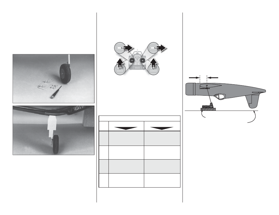
BALANCE YOUR MODEL
NOTE: This section is VERY important and must NOT be
omitted! A model that is not properly balanced will be
unstable and possibly unflyable.
5-3/4" [146mm]
Elevate C.G. Machine
(Fin must not touch table)
❏ 1. The balance point (C.G.) is located 5-3/4" back from
the leading edge of the wing, next to the fuse sides as shown
in the sketch and on the plan. Accurately mark the balance
point on the top of the wing on both sides of the fuselage.
Use thin strips of tape or a felt-tip pen to make the marks.
Hint: Reference the full-size fuse plan to help you locate
the proper balance point. This is the balance point at
which your model should balance for your first flights. After
initial trim flights and when you become more acquainted
with your Corsair, you may wish to experiment by shifting
the balance up to 5/8" forward or backward to change its
flying characteristics. Moving the balance forward may
improve the smoothness and stability, but the model may
then require more speed for takeoff and may become
more difficult to slow for landing. Moving the balance aft
makes the model more agile with a lighter, snappier “feel”
and often improves knife-edge capabilities. In any case,
please start at the location we recommend. Do not at any
time balance your model outside the recommended range.