Top Flite TOPA0410 User Manual
Page 28
- 28 -
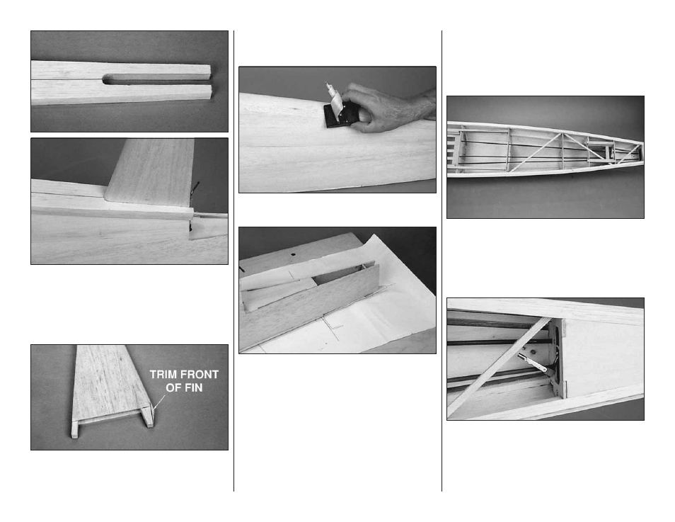
❏ 17. Mark an 11/16" [17.5mm] wide slot, approximately
5-1/8" long, centered on the aft end of the turtledeck top
for the fin to protrude through. Notice that the fin LE
sweeps back. Cut the slot into the tur tledeck top.
Temporarily plug the fin into the slots in formers F-9 and
F-10. Adjust the slot in the turtledeck top if necessary for a
good fit.
❏ 18. Mark the fin where the fin contacts the turtledeck
top. Remove the fin and trim off the LE forward of the
mark. This will allow the fin to be removed after the
turtledeck top is installed.
❏ 19. Tack glue the turtledeck top to the fuse being careful
to not glue the fin in place. Remove the fin and thoroughly
glue the turtledeck top to the fuse with thin CA.
❏ 20. Shape the turtledeck top to match the cross-section
on the plan. A razor plane is helpful for this kind of shaping.
❏ 21. Position the die-cut 1/8" [3.2mm] plywood former
F-12 in position over the fuse plan. Make sure it is
perpendicular to the building board and glue it to the aft
fuse sides. Trim the aft fuse sides flush with the top of the
stab saddle and F-12.
❏ 22. Remove the fuse from the building board and
inspect all the glue joints from the inside. Apply CA to any
open joints.
BUILD THE FUSE BOTTOM
❏ 1. Cut the three 36" [914.4mm] outer pushrod guide
tubes to the lengths required for the rudder and elevator
pushrods (see the fuse side view).
❏ 2. Carefully sand the outside of the three outer pushrod
guide tubes with coarse sandpaper so the glue will adhere
to the formers better. Slide the tubes through the 3/16"
[4.8mm] holes in the formers so that they are positioned
as shown on the fuse plan. Securely glue the tubes to all
the formers.
❏ 3. Thread a nylon torque rod horn onto the threaded
end of the rudder torque rod so that several threads
protrude from the horn. Attach a 4-40 solder clevis to the
torque rod horn.