Top Flite TOPA0410 User Manual
Page 52
- 52 -
❏ 8. Connect the elevator, rudder, aileron, flap and throttle
pushrods to the servo arms.
❏ 9. If you installed a gas engine, install an on/off switch
on the engine that can be manually turned off from the
outside of the cowl. Also an engine on/off switch must be
installed that can be operated from the transmitter. This
can be activated by a separate switch on the transmitter
or by the engine cut switch, found on some transmitters.
INSTALL THE RETRACTS
❏ 1. Follow the instructions included with the pull–pull
steering cable system to connect it to the retractable tail
wheel. Route the air retract tubing through the fuse and
attach it to the air cylinder on the tail wheel. Install the
retractable tail wheel in the fuse.
❏ 2. Install the tail wheel steering servo and connect the
pull–pull steering cables to the servo arm.
❏ 3. Make an air valve tray from leftover 1/8" [3.2mm]
plywood. This assembly can be placed in various
locations. On our test models it was placed in front of the
servo tray, beside the fuel tank. The air valve servo can be
mounted to the front of the servo tray and a hard wood
block glued to the plywood fuse crutch. Install the link rod
assembly between the servo and the air valve following
the retract manufacturer’s instructions. Be sure the servo
does not put side loads on the valve. This may cause the
valve to leak.
❏ 4. Follow the manufacturer’s instructions for connecting
the air line tubing to the air valve, air tank and retractable
tail wheel.
❏ 5. Install the retracts in the wing and route the air lines
through the holes previously drilled in the center spar and
ribs and out the center of the wing. We connected the air
lines in the wing with T-fittings and quick connectors.
❏ 6. Pressurize the air tank and cycle the retracts several
times to check that the retracts do not hang-up anywhere.
❏ 7. Use a solution of soap and water applied to all the air
line joints to detect air leaks. If the joint is leaking the soap
solution will bubble.
ATTACH THE CANOPY
❏ 1. Before permanently installing the canopy, securely
glue your pilot in place on the cockpit floor, if a full cockpit
will not be installed. For the most security, in addition to
glue, screw the base of the pilot to the cockpit floor with a
#4 sheet metal screw (not included) from the underside of
the cockpit floor. If you are installing a full cockpit kit, now
is the time to install it. Follow the installation instructions
included with the cockpit kit.
❏ 2. Place the canopy on the fuselage in the location
shown on the plan. Temporarily hold it in position with tape
or rubber bands.
❏ 3. Use a felt-tip pen to accurately trace the canopy
outline onto the MonoKote film covering. Remove the
canopy.
❏ 4. Without cutting into the balsa, use a sharp hobby
knife to carefully cut and remove a strip of covering 1/16"
[1.6mm] wide, approximately 1/32" (.8mm] inside of the
line you made. Wipe away the line with a paper towel
dampened with alcohol.
❏ 5. Reposition the canopy on the fuse and confirm that it
covers the exposed wood. Glue the canopy to the fuse
with a glue formulated for gluing on canopies such as
Pacer “Formula 560” canopy glue. Hold the canopy in
place with masking tape or rubber bands while the glue
dries.
COOLING NOTES
Model engines require sufficient cooling to provide reliable
operation, good performance and long life. There are two
problems which often present themselves in scale models
with cowlings: lack of air intake area and lack of air outlet
area. A rough rule in figuring such installations is to allow
twice as much outlet area as intake area.
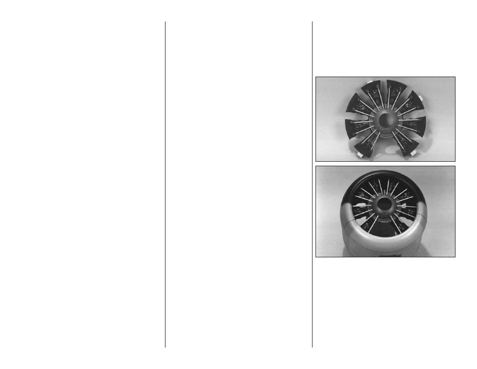
❏ The Corsair model, equipped with a single cylinder
engine, has too much intake area. To work around this
problem, the prototypes were equipped with baffles. A
baffle is used to block intake area where it offers little
benefit and to promote good airflow where it is needed (at
the cylinder head). To enhance the appearance of the
baffle, the Top Flite Corsair Radial Engine can be
mounted on the front of the baffle. The complete assembly
can then be glued in the cowl.
Ample air outlet area must be provided for good cooling.
The bottom of the cowl is a logical place for this since it is
least visible and an opening is needed for the engine
head on the US Engines 41.