TeeJet Matrix 840G User Manual User Manual
Page 62
●
58
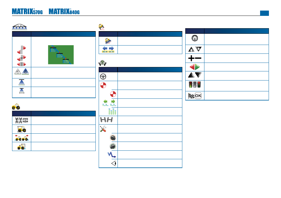
BoomPilot/Single Boom Setup
Icon
Description
Overlap. Determines the amount of overlap allowed when the
boom sections are turned on and off using BoomPilot.
0% Overlap
50% Overlap
100% Overlap
Delay Off/On. Functions as a look ahead for timing the boom
section valves to switch off or on when entering or exiting an
area that has already been applied.
#
Number of Boom Sections. Sets the number of boom sections
(1 to 15 depending on SmartCable or SDM).
Boom Section Width(s). Designates the width for the entire
swath or individual boom sections (depending on SmartCable
or SDM availability on the system).
Vehicle Setup
Icon
Description
Vehicle Type. Selects type of vehicle steering that most closely
represents your vehicle.
Antenna Height. Sets the height of the GPS antenna from the
ground.
Direction to Boom. Sets if the boom is located behind or in front
of the GPS antenna.
Boom Offset Distance. Defi nes the horizontal distance from
GPS Antenna to the boom.
Tilt Gyro Module Setup
Icon
Description
Tilt Correction On/Off. Turns tilt correction on or off.
Level Tilt Positions. Calibrates Tilt Correction.
FieldPilot Setup
Icon
Description
Autosteer. Sets FieldPilot to on or off.
Valve Setup – Valve Frequency, Minimum Duty Cycle
Left/Right and Maximum Duty Cycle.
Valve Frequency. Used to drive the steering valve.
Minimum Duty Cycle. Sets minimum amount of drive required to
begin steering vehicle left/right.
Maximum Duty Cycle. Sets the maximum speed that the wheels
will steer from left to right/right to left (lock to lock).
Valve Test Left/Right. Verifi es steering is directed properly. Used
to fi ne tune oil fl ow to calibrate wheel timing.
Confi gure FieldPilot – Coarse Steering Adjustment, Fine
Steering Adjustment, Deadband and Look Ahead.
Coarse Steering Adjustment. Adjusts how aggressively the
vehicle maintains the guideline in Straight A-B Guidance mode.
Fine Steering Adjustment. Adjusts how aggressively the vehicle
maintains the guideline in Curved A-B Guidance mode.
Deadband. Adjusts steering if it is too choppy/responsive or
vehicle remains consistently off the guideline.
Look Ahead. Used during Straight A-B Guidance mode to adjust
the vehicle’s approach to the guideline.
Commandes générales
Icon
Description
Home Button. Access Home Menu options including Unit Setup,
Vehicle View, Field View, RealView Guidance, Job View and
Boom Monitoring.
Zoom In/Out Buttons. Adjust zoom settings in Vehicle View and
Field View.
Plus & Minus Icons. Used to increase or decrease a setting.
Red = Page Left or Start Test Left.
Green = Page Right or Start Test Right.
Up & Down Icons. Used to change a setting or increase or
decrease the setting.
Stop Light. Green Light = Start Testing, Red Light = Stop
Testing,
Greyed = Testing off.
Finish and OK. Both are used to complete a task.