Field view, Field boundary – TeeJet Matrix 840G User Manual User Manual
Page 48
43
98-05188 R2
www.teejet.com
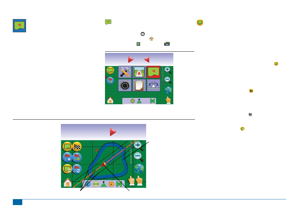
FIELD VIEW
Field View creates a computer-generated image of the
vehicle position and application area from an aerial
perspective. From this screen one can access options for boundary
areas and a marked point or enter World View and Pan modes.
On Screen Guidance
• Guidelines
►Orange – active guidance line
►Black – boundary line
• Points - markers for established points
►Red Point – Return to Point
►Blue Point – Mark A
►Green Point – Mark B
• Coverage Area – illustrates applied area and overlap:
►Blue – one application
►Red – two or more applications
• Zoom In/Out – adjust the map’s visible area.
Button Assistance
• Zoom In/Out & Perspective – adjust the map’s visible area.
Field View
To access the Field View screen.
1. Press HOME BUTTON or press the screen to activate the
icons and select HOME ICON in bottom left corner of screen.
2. Select FIELD VIEW from Home Menu
.
Figure 3-33: Home Menu - Field View
Swath
ha
0.0
0
0.0
km/h
ha
0.53
14.6
5.8
Guidance Bar
Field View
(Zoom In/Out)
or can use Zoom In/Out
Buttons
Vehicle Representation
Pan Mode
World View
Status Bar
Navigation Guidelines
Mark Boundary
Finish Boundary
Mark Point
Return to Point
Cancel Boundary
Cancel Point
Home/Menu Options
or press Home Button
Painted Coverage Area
Figure 3-34: Overview of Field View
Field Boundary
Field boundaries establish application area and determine the no
apply zone.
NOTE: A Field Boundary can be created in either Last Pass
Guidance while in Vehicle View or during any guidance while
in Field View.
To create a fi eld boundary:
1. Drive to a desired location at the perimeter of the fi eld/area.
2. While the vehicle is in motion, press BOUNDARY ICON .
3. Travel the perimeter of the fi eld/area.
4. Finish boundary:
►Travel to within a swath width of the starting point. The
boundary will close automatically (the white guideline will turn
black).
►Press BOUNDARY FINISH ICON . A straight line will
complete the boundary between your current location and the
starting point.
NOTE: If a swath was applied while creating a boundary, the
boundary line will be to the exterior of the applied swath.
NOTE: The BOUNDARY FINISH ICON is not available for
selection (greyed out) until the minimum distance is travelled
(five-times the swath width).
Use CANCEL BOUNDARY ICON to cancel the new fi eld
boundary process and revert to the previous boundary (when
established).