Roadside wiring diagram, D4 - roadside system diagram, Chemical injection pumps – TeeJet TASC-6600 User Manual
Page 76: Printer module (optional)
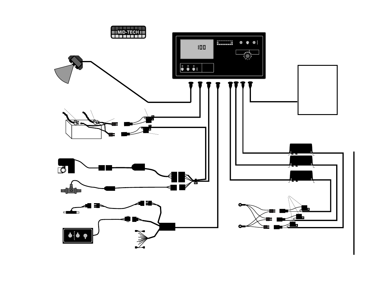
D-8
TASC-6000, 6300, 6600
98-05010
Rev. - 1
+
Vehicle Battery
(12 Volts)
TASC-6300 CONSOLE
Pump Control
Cables
Ground Speed Sensor
120-0000-KIT
Chemical Injection Pumps
Pump Power
Cables
Roadside
Boom Interface
405-0092
1
9
120-xxxx
Printer Module
(Optional)
Flowmeter Interface Cable
405-0044
Flow Control Valve
879-xxxx
Flow Control Cable
( 404-0022)
Fuse,(10 amp)
Power Cable
(401-0010)
Fuse,(5 amp)
Red
Black
Battery Cable
(45-05037)
Fuse,(15 amp)
Neg.
Pos.
Connect
Direct to
BATTERY
Data Logger
(Optional)
Data Link
(Optional)
405-0069-96V
B
O
O
M
S
Handgun/9 Boom
Sense Switchbox
405-0093
Flowsensor
120-0004 or
120-0005
Flow Sensor Cable
402-0009
To existing Boom Switches
Battery Cable
(401-0011)
Valve Driver Cable
( 405-0143)
TASC-6600 CONSOLE
or
Roadside Wiring
Diagram
CHEMICAL APPLICATORS
1
2
3
ON
OFF
Alt.-
Rate
TASC-6300
TOTAL APPLICATION
SPRAYER CONTROL
%Rate
DISPLAY SELECTOR
Speed
Area
Width
Distance
Chem. Applied
Test
Speed
Prime
Total Applied
Chem. Rate
Appl. Rate
CHEMICALS
CARRIER
OFF
SET- UP
DEC.
ON
OPERATE
INC.
1
2
3
4
5
6
7
8 9
BOOMS
Scan
MID-TECH
MIDWEST TECHNOLOGIES, INC.
.
-Ac
Flow
RATE
Gal./
®
Flow Meter
MIDWEST TECHNOLOGIES INC.
2733 East Ash Street
Springfield IL - (217) 753-8424
www.mid-tech.com
'B' Width
Normal
Ground Speed
Override
'C' Width
Handgun
Off
Auto
D4 - ROADSIDE SYSTEM DIAGRAM