Ab c – TeeJet TASC-6600 User Manual
Page 56
B-4
TASC-6000, 6300, 6600
98-05010
Rev. - 1
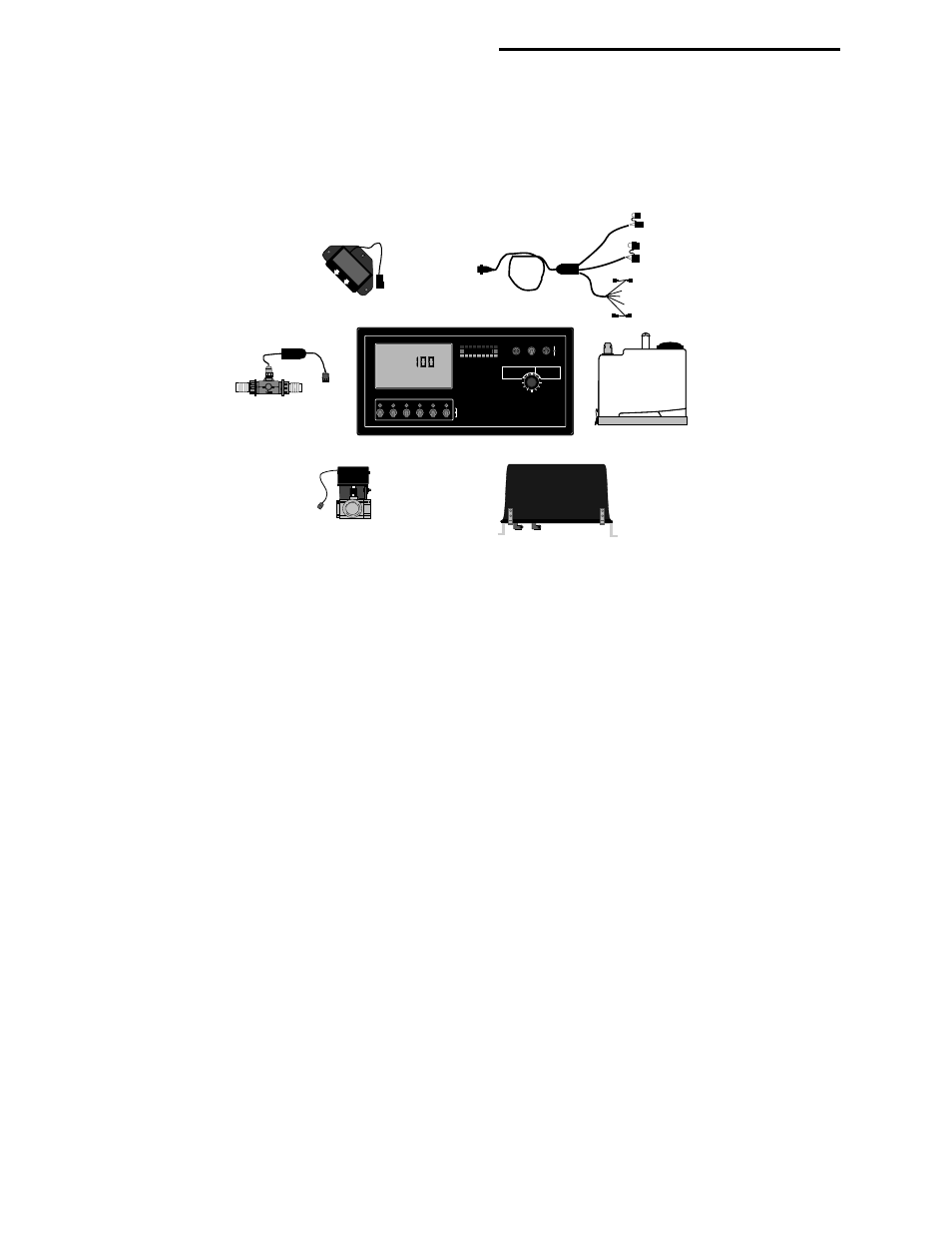
B.2. TASC SYSTEM COMPONENT PARTS
There are seven major components in a complete TASC Injection Control System, a console, ground speed sensor,
flowmeter, flow control valve, boom interface cable, chemical containers, and injection pumps. Each of these compo-
nents is described below so that the operator, will have a general understanding of how each of the parts performs its job.
MID-TECH
MIDWEST TECHNOLOGIES, INC.
CHEMICAL APPLICATORS
1
2
3
ON
OFF
Alt.-
Rate
TASC-6600
TOTAL APPLICATION
SPRAYER CONTROL
%Rate
DISPLAY SELECTOR
Speed
Area
Width
Distance
Chem. Applied
Test
Speed
Prime
Total Applied
Chem. Rate
Appl. Rate
CHEMICALS
CARRIER
OFF
SET- UP
DEC.
ON
OPERATE
INC.
1
2
3
4
5
6
7
8
9
BOOMS
Scan
4
5
6
.
-Ac
Flow
RATE
Gal./
®
A
B
C
TASC Control Console
Speed Sensor
Flowmeter
Flow Control Valve
Chemical Injection Pumps
Chemical Containers
Boom Interface Cable
B.2.1. THE TASC CONTROL CONSOLE
The TASC Control Console is the heart of the system and actually performs three separate functions. The console is a
small computer with a sophisticated program developed by MIDWEST TECHNOLOGIES. The console continually
monitors ground speed, boom width, and current flow rate. As these values change, the console recalculates the required
carrier flow rate and the chemical injection rate of each injection pump and commands the necessary corrections.
Changes in valve settings and pump speeds are almost immediate.
The Control Console allows the operator to command rate changes “ON THE GO”. The operator has complete and
immediate control over the application rate of the main carrier and of each injected chemical. Rates can be altered
independently while the sprayer is operating.
The Control Console informs the operator about the status of the sprayer. TASC Control Console immediately warns the
operator if the system can no longer maintain accurate application. The warnings are both visual and audible, to attract
immediate attention. The large, backlighted LCD also displays instant readouts of carrier application rate and volume
applied, application rate and volume of each chemical applied, vehicle ground speed, active boom width, distance
traveled, and the total area covered while spraying.
B.2.2. FLOWMETER
TASC requires a flowmeter in the main boom feed line to sense and display carrier flow rate. The flowmeter is an
impeller device. This means a specific volume of liquid flowing through the sprayer rotates an impeller a specific
number of revolutions. TASC is able to count the revolutions of the impeller very accurately, allowing the console to
calculate the precise flow rate of the liquid in the main boom supply line.
Sometimes a sprayer is already equipped with a flowmeter. TASC can usually be adapted to work with existing flowme-
ters, as long as they measure the total liquid flow to the sprayer nozzles. Check with your dealer, or the factory, regard-
ing the adaptability of a specific flowmeter.