S2 : gpio input configuration, S3,4 : terminal resistor selection, J6,j7 : jig board connector(socket) – Solvline Eddy DK User Manual
Page 59
Eddy DK Programmer Guide
59
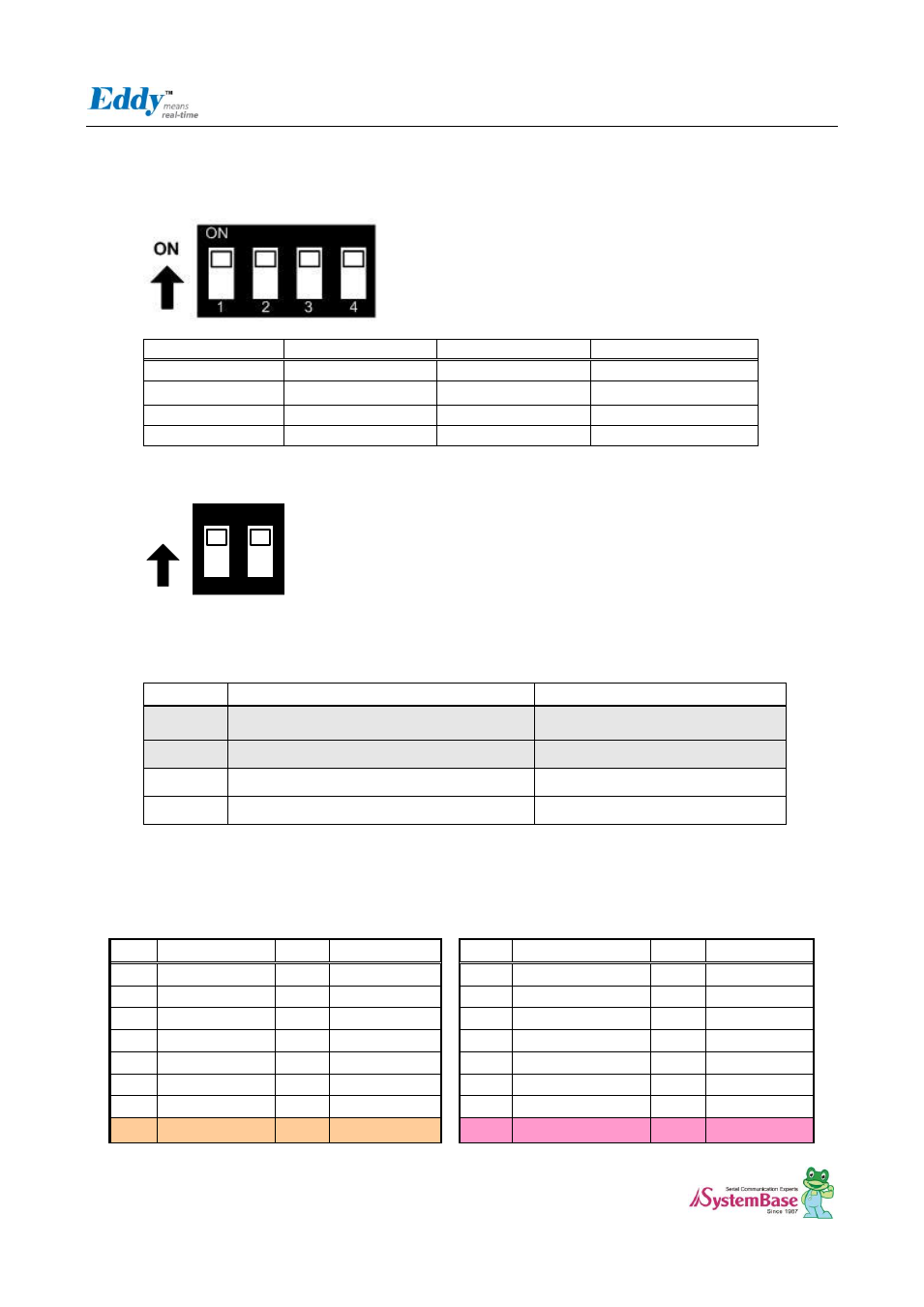
2.6.1.1. S2 : GPIO Input Configuration
After configure PB0-PB4 to input, you can confirm whether the input value is changing with dip switch control.
Switch No
Down Position(OFF)
UP Position(ON)
1
PB0 Value
Low
High
2
PB0 input value
Low
High
3
PB0 input value
Low
High
4
PB0 input value
Low
High
2.6.1.2. S3,4 : Terminal Resistor selection
ON
ON
1
2
COM Port #3 and COM Port #4 is Combo port which support RS422/RS485 interface. Terminal resistors in each port
are configured by switch upon each Terminal Block.
Switch No
Down Position(OFF)
UP Position(ON)
1
RS422 Termination Resistor not connected
RS422 Termination Resistor Connected
2
RS485 Termination Resistor not connected
RS422 Termination Resistor Connected
1
RS422 Termination Resistor not connected
RS422 Termination Resistor Connected
2
RS485 Termination Resistor not connected
RS422 Termination Resistor Connected
2.6.1.3. J6,J7 : JIG Board connector(Socket)
J6
J7
Pin
Signal
Pin
Signal
Pin
Signal
Pin
Signal
1
DTxD
2
DRxD
1
LAN_RX+
2
LAN_TX+
3
TxD0#
4
RxD0#
3
LAN_RX-
4
LAN_TX-
5
RTS0
6
CTS0
5
LAN_Speed
6
LAN_LINK
7
DTR0
8
DSR0
7
PA5
8
PA22
9
DCD0
10
RI0
9
PA30
10
NC
11
TxD1#
12
RxD1#
11
PB0
12
PB1
13
RTS1
14
CTS1
13
PB2
14
PB3
15
3.3V
16
3.3V
15
5V
16
5V