S7:uart select – Solvline Eddy DK User Manual
Page 30
Eddy DK Programmer Guide
30
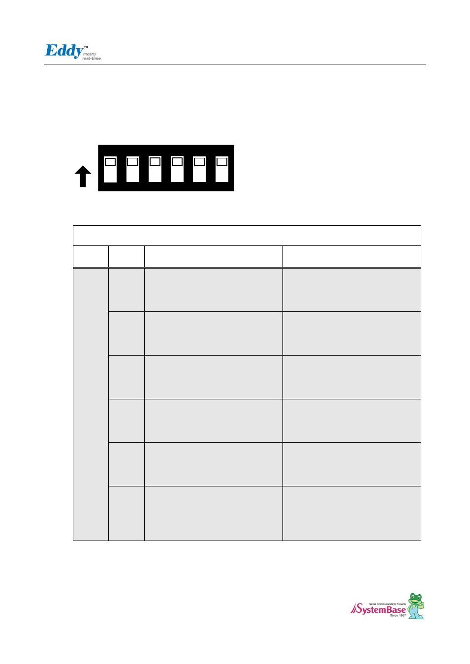
2.4.2.4. S7:UART Select
In order to test Serial Port, UART Select Switches are pulled down. It means that UARTs in CPU are connected to
Serial Port. If switches are pulled up, GPIO Ports are enabled and LEDs are controlled by GPIO Ports. And if Switch
No.6 is pulled up, GPIO ports are connected with the Expansion Headers.
ON
ON
1
2
3
4
5
6
Serial Port & LED
Switch
Bank
Switch
No
Down Position(OFF)
Serial Port Test
UP Position(ON)
GPIO TEST (High : LED On)
S7
1
UART#0 TEST
UART#0 의 TXD, RXD, RTS, CTS
signals are connected with UART#0
RS232 driver IC.
GPIO (PB4, PB5, PB26, PB27) ports are
connected with the GPIO LED of DK
board and disconnected with the
UART#0 RS232 driver IC.
2
UART#0 TEST
UART#0 의 DTR, DSR, DCD, RI signals
are connected with UART#0 RS232
driver IC.
GPIO (PB24, PB22, PB23, PB25) ports
are connected with the GPIO LED of DK
board and disconnected with the
UART#0 RS232 driver IC.
3
UART#1 TEST
UART#1 의 TXD, RXD, RTS, CTS
signals are connected with UART#1
RS232 driver IC.
GPIO (PB6, PB7, PB28, PB29) ports are
connected with the GPIO LED of DK
board and disconnected with the
UART#1 RS232 driver IC.
4
UART#2 TEST
UART#2 의 TXD, RXD, RTS, CTS
signals are connected with UART#2
RS422/485 driver IC.
GPIO (PB8, PB9, PA4, PA5) ports are
connected with the GPIO LED of DK
board and disconnected with the
UART#2 RS422/485 driver IC.
5
UART#3 TEST
UART#3 의 TXD, RXD, RTS, CTS
signals are connected with UART#3
RS422/485 driver IC.
GPIO (PB10, PB11, PC8, PC10) ports
are connected with the GPIO LED of DK
board and disconnected with the
UART#3 RS422/485 driver IC.
6
For Serial Port & GPIO Test
Serial Port and GPIO LED of DK board
are enabled.
Connect to Expansion Header
UART#0~#3 and GPIO LEDs are
disconnected with the Eddy-CPU board
and directly connected with the
Expansion Header(J2, J4)