Reznor UDBS Unit Installation Manual User Manual
Page 39
Form I-UDB, P/N 202658 R14, Page 39
10.2.8 Combustion Air
Pressure Switch
See
FIGURE 22, page 35, for location. (NOTE: Depending on date of manufacture and
size, pressure switch may not be in the location indicated. Check the control bracket
on the bottom of the compartment or further down on the compartment wall.) If it is
determined that the pressure switch needs replacing, use only the factory-authorized
replacement part that is designed for the model and size of heater being serviced.
NOTE: A unit operating above 6000 ft (1830M) elevation requires a high altitude pres-
sure switch. See Paragraph 3.2.
10.2.9 Limit Control
If it is determined that the limit control needs replacing, use only a factory-
authorized replacement part that is designed for the size of heater.
For approximate limit location, see
FIGURE 22, page 35.
The combination gas valve must be checked annually to ensure that the valve is shut-
ting off gas flow completely.
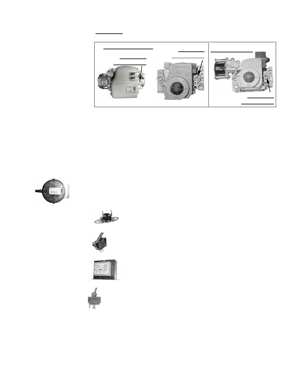
Instructions:
1) Locate the 1/8” NPT pressure tap on the combination valve.
NOTE: Operational
pressure settings and
instructions for checking
pressure settings are in
Paragraph 6.1.
FIGURE 27 - Pressure
Tap for Checking Gas
Flow Shutoff
2) With the manual valve turned off to prevent flow to the gas valve, connect a
manometer to the 1/8” outlet pressure tap in the valve. NOTE: A manometer (fluid-
filled gauge) is recommended.
3) Turn the manual valve to the ON position and the heater OFF. Use your finger to
fully block the main burner orifice for several seconds. Observe the manometer
with the orifice blocked, and if any pressure is indicated, the gas valve is leaking.
A leaking gas valve must be replaced before the heater is put back in
operation.
10.2.10. Door Switch
- UDBS only
If it is determined that the door switch needs replacing, use only a factory-
authorized replacement part that is designed for the heater.
For approximate switch location, see
FIGURE 22, page 35.
10.2.11 Transformer
See
FIGURE 22, page 35, for location. Use a voltmeter to verify that
there are 24 volts output from the transformer. If the transformer is not
functioning, it must be replaced. Use a replacement transformer identi-
cal to the factory-installed model.
10.2.13 Vent or Vent/
Combustion Air
System
The disconnect switch is located in the sealed electrical box inside the control
compartment with the toggle on the rear of the heater.
If it is determined that the disconnect switch needs replacing, use only the fac-
tory-authorized replacement part that is designed for the heater. Always replace
electrical box cover.
10.2.12 Disconnect
Switch - UDBS only
Check the complete system at least once a year. Inspection should include all joints,
seams, concentric adapter box (UDBS), inlet air guard or inlet air cap (UDBS), and the
vent terminal cap. Clean openings. Replace any defective parts.
Single-Stage Valves
1/8” Outlet
Pressure Tap
1/8” Outlet
Pressure Tap
Two -Stage Valve
1/8” Outlet
Pressure Tap