2 combustion air - models udbp, 0 mechanical (cont’d), 1 gas piping and pressures (cont’d) – Reznor UDBS Unit Installation Manual User Manual
Page 16
Form I-UDB, P/N 202658 R14, Page 16
Combustion Air
Requirements for a
Heater Located in
a Confined Space -
applies to Model UDBP
6.2 Combustion Air - Models UDBP
This heater must be supplied with the air that enters into the combustion process and is
then vented to the outdoors. Sufficient air must enter the equipment location to replace
that exhausted through the heater vent system. In the past, the infiltration of outside air
assumed in heat loss calculations (one air change per hour) was assumed to be suf-
ficient. However, current construction methods using more insulation, vapor barriers,
tighter fitting and gasketed doors and windows, weather-stripping, and/or mechanical
exhaust fans may now require the introduction of outside air through wall openings or
ducts.
The requirements for combustion and ventilation air depend upon whether the unit is
located in a confined or unconfined space. An “unconfined space” is defined as a space
whose volume is not less than 50 cubic feet per 1000 BTUH of the installed appliance.
Under ALL conditions, enough air must be provided to ensure there will not be a
negative pressure condition within the equipment room or space.
WARNING
Model UDBP power-vented unit heaters are designed to take
combustion air from the space in which the unit is installed and
are not designed for connection to outside combustion air intake
ducts. Connecting outside air ducts voids the warranty and could
cause hazardous operation. See Hazard Levels, page 2.
Do not install a unit in a confined space without providing wall openings leading to and
from the space. Provide openings near the floor and ceiling for ventilation and air for
combustion as shown in
FIGURE 11, depending on the combustion air source as noted
in Items 1, 2, and 3 below.
Add total BTUH of all appliances in the confined space and divide by figures below for
square inch free area size of each (top and bottom) opening.
(Note: For Model
UDBS, see
Venting Manual
for combustion air
requirements.)
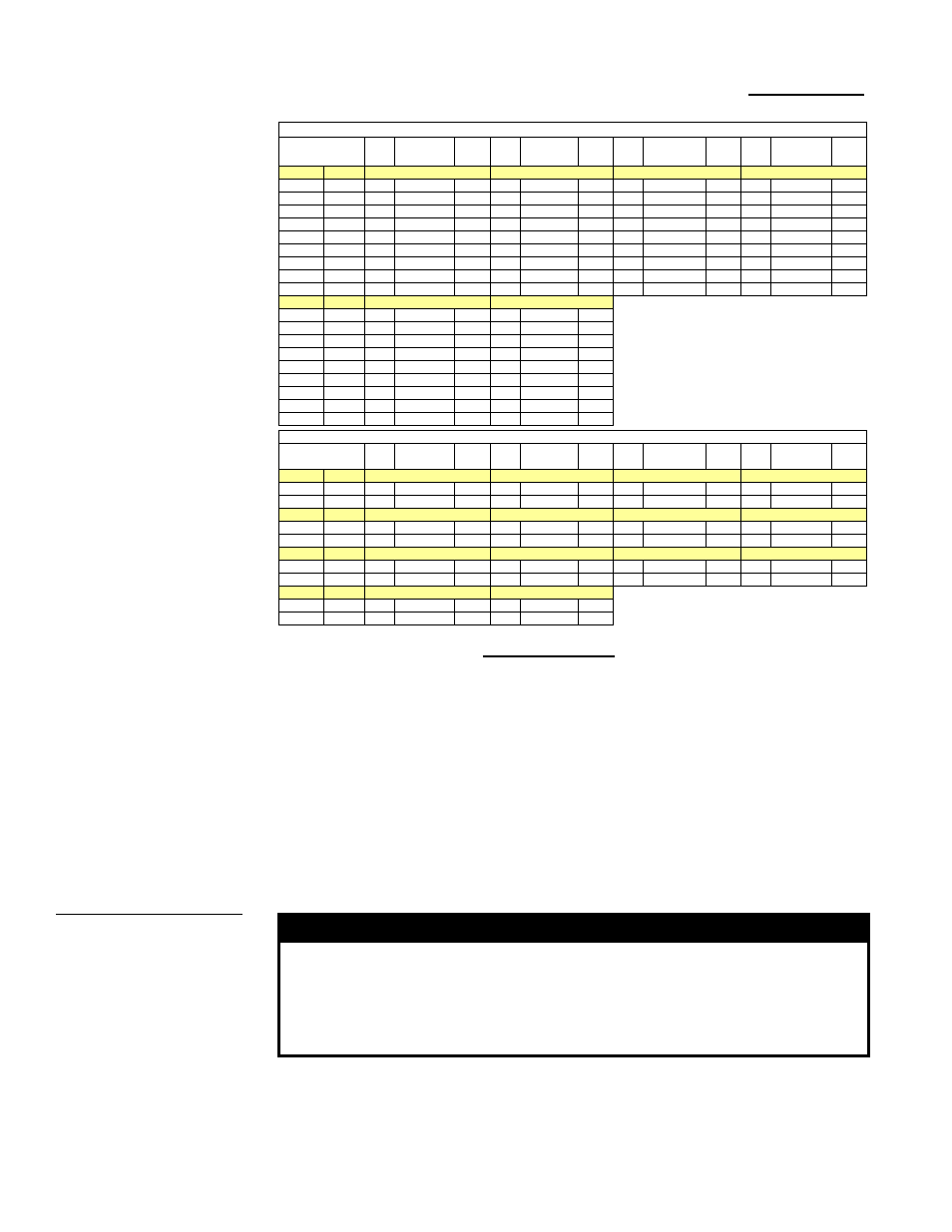
6.0 Mechanical
(cont’d)
6.1 Gas Piping and Pressures (cont’d)
6.1.3 Derate by Valve Outlet Pressure Adjustment for High Altitude
Operation (cont’d)
High Altitude
Capacity Changes
(cont’d)
BTUH Inputs and Capacities by Altitude in the UNITED STATES for Model UDBP and Model UDBS (cont'd)
ALTITUDE
Normal
Input
Thermal Output
Capacity
Minimum
Input
Normal
Input
Thermal Output
Capacity
Minimum
Input
Normal
Input
Thermal Output
Capacity
Minimum
Input
Normal
Input
Thermal Output
Capacity
Minimum
Input
Feet
Meters
Size 200
Size 225
Size 250
Size 300
0-2000
0-610
200000
166000
140000 225000
186750
157500 250000
207500
175000 300000
249000
210000
2001-3000 611-915 188000
156040
131600 211500
175545
148050 235000
195050
164500 282000
234060
197400
3001-4000 916-1220 184000
152720
128800 207000
171810
144900 230000
190900
161000 276000
229080
193200
4001-5000 1221-1525 180000
149400
126000 202500
168075
141750 225000
186750
157500 270000
224100
189000
5001-6000 1526-1830 176000
146080
123200 198000
164340
138600 220000
182600
154000 264000
219120
184800
6001-7000 1831-2135 172000
142760
120400 193500
160605
135450 215000
178450
150500 258000
214140
180600
7001-8000 2136-2440 168000
139440
117600 189000
156870
132300 210000
174300
147000 252000
209160
176400
8001-9000 2441-2745 164000
136120
114800 184500
153135
129150 205000
170150
143500 246000
204180
172200
9001-10000 2746-3045 160000
132800
112000 180000
149400
126000 200000
166000
140000 240000
199200
168000
Feet
Meters
Size 350
Size 400
0-2000
0-610
350000
290500
245000 400000
332000
280000
2001-3000 611-915 329000
273070
230300 376000
312080
263200
3001-4000 916-1220 322000
267260
225400 368000
305440
257600
4001-5000 1221-1525 315000
261450
220500 360000
298800
252000
5001-6000 1526-1830 308000
255640
215600 352000
292160
246400
6001-7000 1831-2135 301000
249830
210700 344000
285520
240800
7001-8000 2136-2440 294000
244020
205800 336000
278880
235200
8001-9000 2441-2745 287000
238210
200900 328000
272240
229600
9001-10000 2746-3045 280000
232400
196000 320000
265600
224000
BTUH Inputs and Capacities by Altitude in CANADA for Models UDBP and UDBS
ALTITUDE
Normal
Input
Thermal Output
Capacity
Minimum
Input
Normal
Input
Thermal Output
Capacity
Minimum
Input
Normal
Input
Thermal Output
Capacity
Minimum
Input
Normal
Input
Thermal Output
Capacity
Minimum
Input
Feet
Meters
Size 30
Size 45
Size 60
Size 75
0-2000
0-610
30000
24600
30000 45000
37350
45000 60000
49800
42000 75000
62250
52500
2001-4500 611-1373 27000
22140
27000 40500
33615
40500 54000
44820
37800 67500
56025
47250
Feet
Meters
Size 100
Size 125
Size 150
Size 175
0-2000
0-610
105000
88200
73500 120000
100800
84000 150000
124500
105000 175000
145250
122500
2001-4500 611-1373 94500
79380
66150 108000
90720
75600 135000
113400
94500 157500
132300
110250
Feet
Meters
Size 200
Size 225
Size 250
Size 300
0-2000
0-610
200000
166000
140000 225000
186750
157500 250000
207500
175000 300000
249000
210000
2001-4500 611-1373 180000
151200
126000 202500
170100
141750 225000
189000
157500 270000
226800
189000
Feet
Meters
Size 350
Size 400
0-2000
0-610
350000
290500
245000 400000
332000
280000
2001-4500 611-1373 315000
264600
220500 360000
302400
252000