0 maintenance and service (cont’d), 2 maintenance procedures (cont’d) – Reznor UDBS Unit Installation Manual User Manual
Page 38
Form I-UDB, P/N 202658 R14, Page 38
10.0 Maintenance
and Service
(cont’d)
10.2 Maintenance
Procedures
(cont’d)
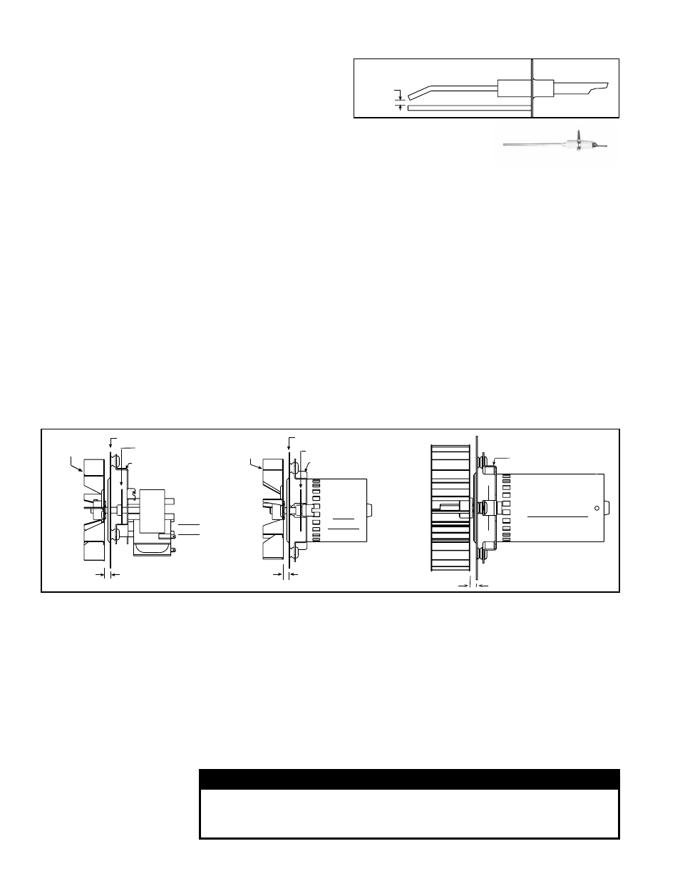
FIGURE 26 - Venter
Wheel Position on
Shaft
5/16 (8mm) inside
5/16 (8mm) inside
Venter Wheel,
Sizes 30-75
Venter Motor Plate
Fan
Motor Mounting
Bracket
Venter
Motor for
Sizes
100-175
Venter Wheel,
Sizes 100-175
Venter Motor Plate
Motor Mounting Bracket
Fan
Venter
Motor for
Sizes
30-75
7/16 (11mm) inside
Venter Wheel
Motor Mounting Bracket
Venter Motor for
Sizes 200-400A
10.2.5 Venter Motor
and Wheel
Remove dirt and grease from the motor casing, the venter housing, and the venter
wheel. Venter motor bearings are permanently lubricated. Follow these instructions for
replacement of the venter motor and wheel assembly. Keep all hardware removed to
be used in re-assembling and installing the replacement parts.
Replacement Instructions
1. Turn off the gas and disconnect the electric power.
2. Open the burner/control compartment access panel.
3. Disconnect the three venter motor wires at the DSI control, capacitor wires at the
capacitor (if applicable), and ground screw (located on the control panel).
4. Sizes 30 and 45 - Disconnect the gas train and move it out of the way. Disconnect
the gas supply at the union outside of the cabinet. At the gas valve, mark and
disconnect the wires. Carefully remove the burner orifice and orifice adapter
locking nut. Slide the orifice adapter out through the bracket on the burner pushing
the gas train to the right. This will move the gas train out of the way.
5. Holding the venter motor, remove the three or four screws that attach the venter
motor mounting plate to the venter housing. Remove the motor and wheel
assembly from the heater.
6. Re-assemble with the replacement venter motor and wheel assembly. See
FIGURE 26.
7. Follow the wiring diagram to connect the venter wires.
8. Sizes 30 and 45 - Reconnect the gas supply at the union outside of the cabinet.
Leak test the connection with leak detecting solution.
9. Replace the access panel. Restore power to the heater and turn on the gas.
Light, following the instructions on the lighting instruction plate. Check for proper
operation.
10.2.6 Blower, Motor,
and Guards
10.2.7 Operating
Gas Valve
Carefully remove external dirt accumulation and check wiring connections.
WARNING
The operating valve is the prime safety shutoff. All gas supply
lines must be free of dirt or scale before connecting to the unit to
ensure positive closure.
Remove dirt and grease from the motor, blower, and guards. Check the belt for wear
and proper tension.
The motor supplied has lifetime lubrication and sleeve bearings. If the motor has been
replaced with one that has oil cups or grease fittings, lubricate the motor.
Check current draw to motor rating plate.
Flame Sensor - Refer to FIGURE 22 and locate the flame
sensor. Disconnect the wire; remove the screw and the
flame sensor. Clean with an emery cloth.
Flame Sensor
10.2.4 Ignition System (cont’d)
FIGURE 25 - Ignitor
showing required Spark
Gap measurement
1/8 inch
(3.2mm)