1 power supply setup, 2 cables for serial communication, 1 usb connection (recommended) – Maxim Integrated 71M6541 Demo Board User Manual
Page 8: 2 serial connection (via optional debug board), Power supply setup, Cables for serial communication, Table 1-1: jumper settings on debug board, Table 1-2: straight cable connections, Table 1-3: null-modem cable connections
71M6541 Demo Board REV 3.0 User’s Manual
8
Rev 4.0
1.7.1 POWER SUPPLY SETUP
There are several choices for the meter power supply:
o
Internal (using the AC line voltage). The internal power supply is only suitable when the voltage ex-
ceeds 100V RMS. To enable the internal supply, a jumper needs to be installed across JP6 on the top
of the board.
o
External 5.0VDC connector (J20) on the Demo Board.
1.7.2 CABLES FOR SERIAL COMMUNICATION
1.7.2.1 USB Connection (Recommended)
A standard USB cable can be used to connect the Demo Board to a PC running HyperTerminal or a similar se-
rial interface program. A suitable driver, e.g., the FTDI CDM Driver Package, must be installed on the PC to en-
able the USB port to be mapped as a virtual COM port. The driver can be found on the FTDI web site
(www.ftdichip.com).
See Table 3-1 for correct placement of jumper JP5 depending on whether the USB connection or the serial
connection via the Debug Board is used.
1.7.2.2 Serial Connection (via Optional Debug Board)
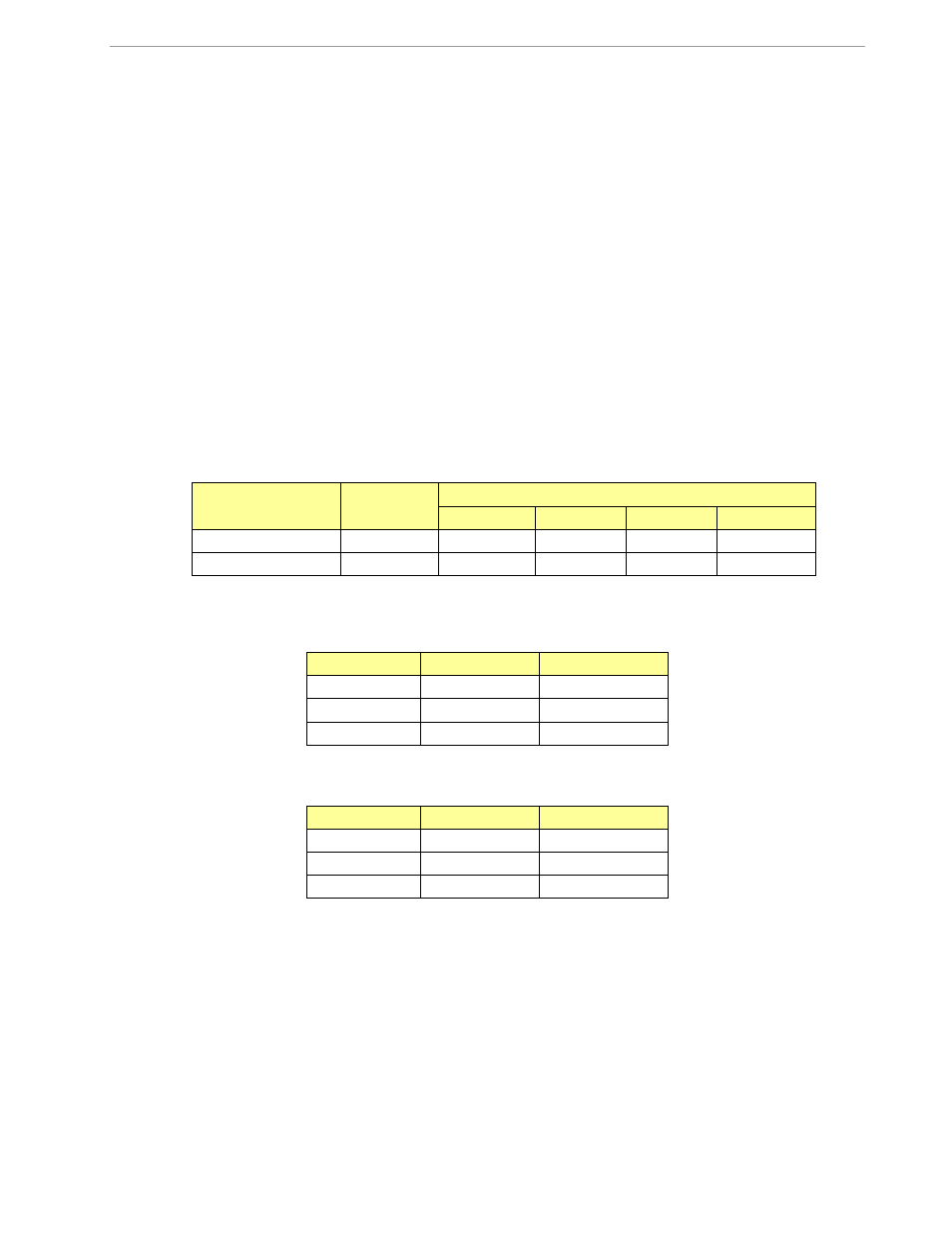
For connection of the DB9 serial port of the Debug Board to a PC serial port (COM port), either a straight or a
so-called “null-modem” cable may be used. JP1 and JP2 are plugged in for the straight cable, and JP3/JP4 are
empty. The jumper configuration is reversed for the null-modem cable, as shown in Table 1-1.
Cable Configura-
tion
Mode
Jumpers on Debug Board
JP1
JP2
JP3
JP4
Straight Cable
Default
Installed
Installed
--
--
Null-Modem Cable
Alternative
--
--
Installed
Installed
Table 1-1: Jumper Settings on Debug Board
JP1 through JP4 can also be used to alter the connection when the PC is not configured as a DCE device. Ta-
ble 1-2 shows the connections necessary for the straight DB9 cable and the pin definitions.
PC Pin
Function
Demo Board Pin
2
TX
2
3
RX
3
5
Signal Ground
5
Table 1-2: Straight Cable Connections
Table 1-3 shows the connections necessary for the null-modem DB9 cable and the pin definitions.
PC Pin
Function
Demo Board Pin
2
TX
3
3
RX
2
5
Signal Ground
5
Table 1-3: Null-modem Cable Connections
See Table 3-1 for correct placement of jumper JP5 on the Demo Board depending on whether the USB connec-
tion or the serial connection via the Debug Board is used.