7 demo board test setup, Demo board test setup, Demonstration meter – Maxim Integrated 71M6541 Demo Board User Manual
Page 7
71M6541 Demo Board REV 3.0 User’s Manual
7
Rev 4.0
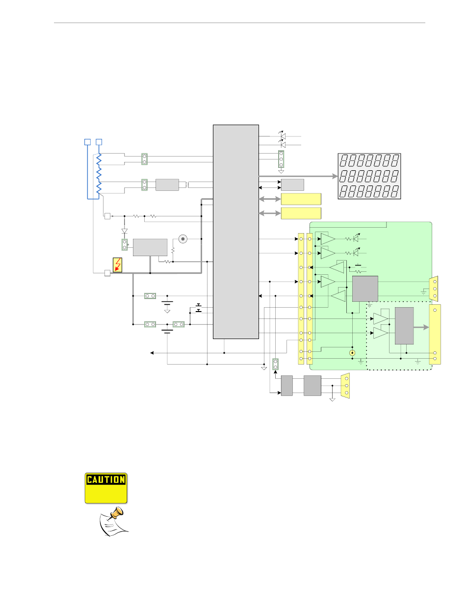
1.7 DEMO BOARD TEST SETUP
Figure 1-1 shows the basic connections of the Demo Board plus optional Debug Board with the external equip-
ment. The PC can be connected via the USB Interface (CN1). For stand-alone testing (without AC voltage) the
Demo Board maybe powered via the 5.0 VDC input (J20). The optional Debug Board must be powered with its
own 5 VDC power supply.
Figure 1-1: 71M6541-DB REV3.0 Demo Board with optional Debug Board: Basic Connections
The Demo Board contains all circuits necessary for operation as a meter, including display, calibration LEDs,
and internal power supply. Communication with a PC USB port is provided via connector CN1. The optional
Debug Board uses a separate power supply, and is optically isolated from the Demo Board. It interfaces to a PC
through the USB connector.
It is recommended to set up the demo board with no live AC voltage connected, and to
connect live AC voltages only after the user is familiar with the demo system.
All input signals are referenced to the V3P3A (3.3V power supply to the chip).
DEMONSTRATION METER
IA
IB
NEUTRAL
IAP
IBP
V3P3A
VA
LINE
GND
V3P3
GND
5.0 VDC
Input
EEPROM
ICE Connector
SEGDIO52
SEGDIO10
TX
RX
DB9
to PC
COM Port
6541
Single Chip Meter
TMUXOUT
TMUX2OUT
3.3V or 5V
LCD
SDCK
SDATA
IAN
IBN
V3P3SYS
Wh
VARh
SEGDIO0/WPULSE
SEGDIO1/VPULSE
PULSE OUTPUTS
SEGDIO7/YPULSE
SEGDIO6/XPULSE
V3P3SYS
V3P3D
VBAT
Battery 2
(optional)
J13
PB
On-board components
powered by V3P3D
OPTO
OPTO
OPTO
OPTO
OPTO
5V DC
V5_DBG
GND_DBG
V5_DBG
V5_DBG
RS-232
INTERFACE
GND_DBG
V5_DBG
OPTO
OPTO
FPGA
06/03/2010
V5_NI
CE HEARTBEAT (1Hz)
MPU HEARTBEAT (5Hz)
DEBUG BOARD (OPTIONAL)
RTM INTERFACE
JP21
J21
4
15, 16
13, 14
6
6
8
12
10
3
1
2
5, 7,
9, 11
GND
V3P3SYS
JP6
J1
PULSE A
PULSE B
Power Supply
J5
68 Pin
Connector
VBAT_RTC
Battery 1
(optional)
RESET
JP56
J12
JP20
SPI Connector
J14
J19
JP5
CN1
Isolator
RESET
PB
USB
Interface
External
Shunts
6601
J5
J3
Serial/USB
Converter
Iso-
GND
Load
L
N