7 compensating for non-linearities, Compensating for non-linearities – Maxim Integrated 71M6541 Demo Board User Manual
Page 45
71M6541 Demo Board REV 3.0 User’s Manual
45
Rev 4.0
2.3.7 COMPENSATING FOR NON-LINEARITIES
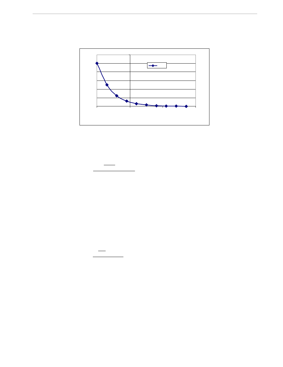
Nonlinearity is most noticeable at low currents, as shown in Figure 2-9, and can result from input noise and
truncation. Nonlinearities can be eliminated using the
QUANT
variable.
Figure 2-9: Non-Linearity Caused by Quantification Noise
The error can be seen as the presence of a virtual constant noise current. While 10mA hardly contribute any er-
ror at currents of 10A and above, the noise becomes dominant at small currents.
The value to be used for
QUANT
can be determined by the following formula:
LSB
IMAX
VMAX
I
V
error
QUANT
⋅
⋅
⋅
−
=
100
Where error = observed error at a given voltage (V) and current (I),
VMAX = voltage scaling factor, as described in section 1.8.3,
IMAX = current scaling factor, as described in section 1.8.3,
LSB = QUANT LSB value = 7.4162*10
-10
W
Note that different values for the LSB of
QUANT
apply, depending on which type of code is used. The LSB val-
ues are listed in the IC data sheet for standard CE codes.
Example: Assuming an observed error for a meter with local sensors as in Figure 2-9, we determine the error at
1A to be +0.5%. If VMAX is 600V and IMAX = 208A, and if the measurement was taken at 240V, we determine
QUANT as follows:
QUANT LSB = 1.04173*10
-9
VMAX IMAX = 1.3*10
-4
9230
_
1
240
100
5
.
0
−
=
⋅
−
=
LSB
QUANT
QUANT
QUANT
is to be written to the CE location given by the IC data sheet. It does not matter which current value is
chosen as long as the corresponding error value is significant (1% error at 1.0 A used in the above equation will
produce the same result for
QUANT
).
Input noise and truncation can cause similar errors in the VAR calculation that can be eliminated using the
QUANT_VAR
variable.
QUANT_VAR
is determined using the same formula as
QUANT
.
The internal power supply generates a ripple on the supply and ground nets that is 90° phase shifted with re-
spect to the AC supply voltage. This affects the accuracy of the VARh measurements. If optimization of the
VARh accuracy is required, this can be done by writing a value into the
QUANT_VAR
register of the CE
0
2
4
6
8
10
12
0.1
1
10
100
I [A]
e
rr
o
r [
%
]
error