Table 1-7: bits in the mpu status word – Maxim Integrated 71M6541 Demo Board User Manual
Page 29
71M6541 Demo Board REV 3.0 User’s Manual
29
Rev 4.0
3
Three-phase ICs only. Some CE codes calculate neutral current rather than measuring it. Consult the CE documenta-
tion.
4
Only in systems with two current sensors.
5
High accuracy use of this feature may require a calibrated clock.
6
IEC 62056 Manufacturers’ IDs are allocated by the FLAG Association Limited. Maxim Integrated does not own or profit
from the FLAG association. Maxim Integrated’s default id may not conform, and is for demonstration purposes only.
7
Nothing in the document should be interpreted as a guarantee of conformance to a third-party software specification.
Conformance testing is the responsibility of a meter manufacturer.
8
May require calibration for best accuracy.
9
Calibration item in high-precision “H” series meters (71M6541H only).
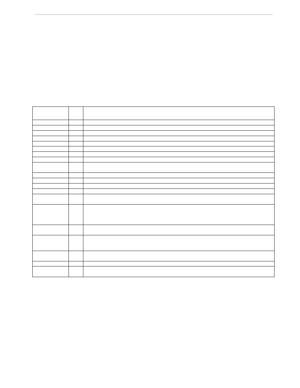
Table 1-7: Bits in the MPU Status Word
Name
Bit
No.
Explanation
MINIA
0
IA is below IThrshld. Current for this phase is in creep.
MINIB
1
IB is below IThrshld. Current for this phase is in creep.
MINIC
2
IC is below IThrshld. Current for this phase is in creep.
MINVA
3
VA is below VThrshld. Voltage for this phase is in creep.
MINVB
4
VB is below VThrshld. Voltage for this phase is in creep.
MINVC
5
VC is below VThrshld. Voltage for this phase is in creep.
CREEPV
6
All voltages are below VThrshld.
CREEP
7
There is no combination of current and voltage on any phase.
SOFTWARE
8
A software defect was detected. error_software() was called. For example: An impossible value
occurred in a selection, or the timers ran out.
NEUTRAL
9
Neutral current was above in_limit for more than in_wait seconds.
SPURIOUS
10
An unexpected interrupt was detected.
SAG
11
Voltage was below VThrshld for more than in_wait seconds
DEMAND
12
Demand was too big (too many watts) to be credible.
CALIBRATION
13
Set after reset if the read of the calibration data has a bad checksum, or is from an earlier ver-
sion of software. The default values should be present.
RTC_UNSET
14
Set when the clock’s current reading is A) Obtained after a cold start, indicating that there was
no battery power, and therefore the clock has to be invalid. B) More than a year after the previ-
ously saved reading, or C) Earlier than the previously saved reading. In this case, the clock’s
time is preserved, but the clock can’t be trusted.
HARDWARE
15
An impossible hardware condition was detected. For example, the software times out waiting
for RTC_RD to become zero.
BATTERY_BAD
16
Just after midnight, the demo code sets this bit if VBat < VBatMin. The read is infrequent to
reduce battery loading to very low values. When the battery voltage is being displayed, the
read occurs every second, for up to 20 seconds.
REGISTER_BAD
17
Set after reset when the read of the power register data has a bad longitudinal redundancy
check or bad software version in all 5 copies. Unlikely to be an accident.
RTC_TAMPER
18
Clock set to a new value more than two hours from the previous value.
TAMPER
19
Tamper was detected. Normally this is a power tamper detected in the creep logic. For exam-
ple, current detected with no voltage.
Table 1-8 contains LSB values for the CE registers used in the CE code for EQU 0 and EQU 1. All values are
based on the following settings:
•
Gain in amplifier for IAP/IAN pins selected to 1.
•
71M6103 or 71M6113 Remote Sensor Interface is used.
Note that some of the register contents can be zeroed out by the MPU when it applies functions contained in its
creep logic.