Maxim Integrated 71M6541 Demo Board User Manual
Page 13
71M6541 Demo Board REV 3.0 User’s Manual
13
Rev 4.0
Auxiliary Commands:
Typing a comma (“,”) repeats the command issued from the previous command line. This is very helpful when
examining the value at a certain address over time, such as the CE DRAM address for the temperature (0x40).
The slash (“/”) is useful to separate comments from commands when sending macro text files via the serial in-
terface. All characters in a line after the slash are ignored.
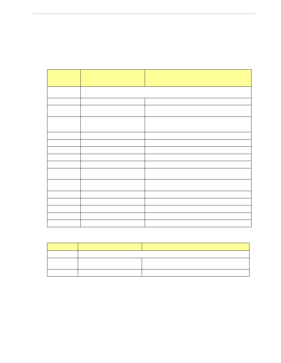
Commands controlling the CE, TMUX and the RTM:
C
COMPUTE ENGINE,
MEMORY, AND CALIBRA-
TION CONTROL
Comment
Description:
Allows the user to enable and configure the compute engine, store and recall configurations, and
initiate calibration.
Usage:
C [option] [argument]
Command
combinations:
CEn
Compute Engine Enable (1
Enable,
0
Disable)
CTn.m
Selects the signal for the TMUX output pins (n = 1 for
TMUXOUT, n = 2 for TMUX2OUT). m is interpreted as a dec-
imal number.
CREn
RTM output control (1
Enable, 0 Disable)
CRSa.b.c.d
Selects CE addresses for RTM output
CLS
Stores calibration and other settings to EEPROM.
CLR
Restores calibration and other settings from EEPROM.
CLD
Restores calibration and other settings to defaults.
CLB
Start auto-calibration based on voltage (MPU address 0x17,
current (MPU 0x18), and duration (MPU 0x16) in seconds.
CLC
Apply machine-readable calibration control (Intel Hex-
Records).
CPA
Start the accumulating periodic pulse counters.
CPC
Clear the pulse counters
CPDn
Activate pulse counters for n seconds
Example:
CE0
Disables CE, (“SYS will stop blinking on the LCD).
CT1.3
Selects the VBIAS signal for the TMUX output pin
Commands for Identification and Information:
I
INFORMATION MESSAGES
Comment
Description:
Allows the user to read information messages.
Usage:
I
Sends complete demo code version information on serial inter-
face.
M0
Displays meter ID on LCD.
The I command is mainly used to identify the revisions of Demo Code and the contained CE code.