1 71m6541-db electrical schematic, 71m6541-db electrical schematic, Power down circuit – Maxim Integrated 71M6541 Demo Board User Manual
Page 65: Off-page connectors
71M6541 Demo Board REV 3.0 User’s Manual
65
Rev 4.0
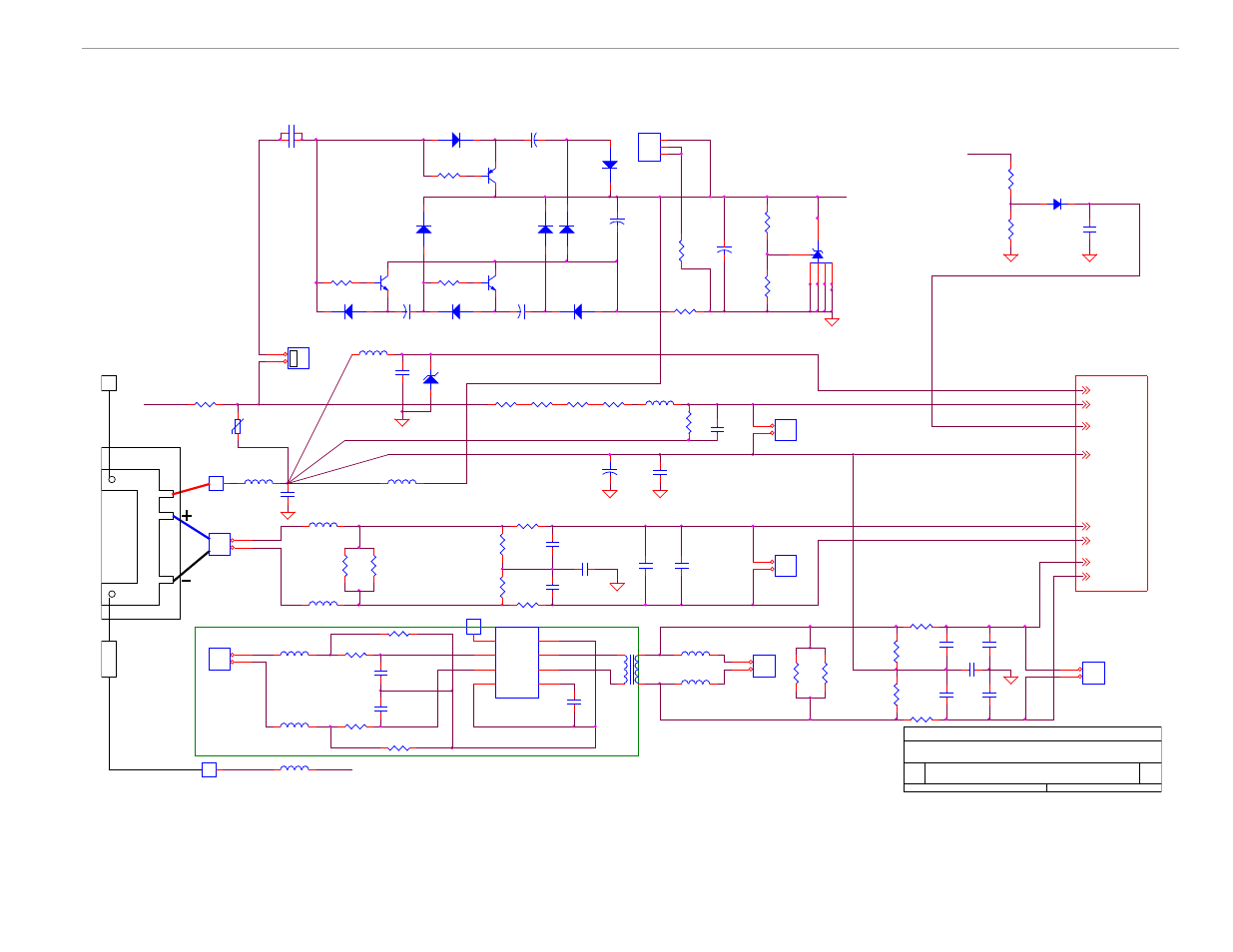
4.1 71M6541-DB ELECTRICAL SCHEMATIC
Figure 4-1: 71M6541-DB REV 3.0 Demo Board: Electrical Schematic 1/2
VA
BOARD_SUPPLY
C16
1000pF
NEUTRAL_IN
GND_R6000
IBP
R141
100
TP3
TESTPOINT
DNP
1
1
RV1
VARISTOR
1
2
NEUTRAL
C56
0.1uF
NEUTRAL_IN
J8
1
1
2
2
J4
1
1
JP6
1
1
2
2
C34
33uF/6.3V
For Optional CT
IBP
IBN
C58
100pF
L13
Ferrite Bead 600ohm
C9
1000pF
R39
4.7K
0805
R47
270K
0805
R64
270K
0805
R66
2M
R32
750
805
R6
8.20K
0805
C14
1000pF
IAN_IN
IAP_IN
R25
3.4
1206
DNP
L2
Ferrite Bead 180ohm
L3
Ferrite Bead 180ohm
C25
1000pF
DNP
R24
3.4
1206
DNP
C12
1000pF
DNP
C68
0.1uF
IAP_IN
R57
0
R7
2M
IAN_IN
J3
1
1
2
2
V3P3A
R86
10K
DNP
R87
10K
DNP
IA_IN
R26
0
Note: C29, C32, and C34 have been reversed
on the silk screen. This schematic is
correct!
L11
Ferrite Bead 600ohm
LINE
IAP
SEGDIO8
+
C40
470uF
IAN
LINE
SEGDIO8
NEUTRAL_IN
L14
Ferrite Bead 600ohm
Isolated Sensor and signal transform er
C8
0.22uF
275V
IAP
C11
0.47uF
L12
Ferrite Bead 600ohm
D2
S1J-E3
R13
20K
R14
6.04K
R19
150
R18
30K
D10
1N4148WS
R20
8.06K
Q2
BC857
Q3
BCX70
Q4
BCX70
D7
1N4148WS
C13
100uF/15V
C26
100uF/15V
D11
1N4148WS
D13
1N4148WS
D4
1N4148WS
C29
1000uF/6V
D3
1N4148WS
C32
100uF/15V
D14
1N4148WS
C4
0.1uF
D15
1N4148WS
R21
25.2K
Negative Supply 3
Positive Supply
Shunt Regulator
Negative Supply 1
Negative Supply 2
IBN
IB
J10
1
1
2
2
D9
UCLAMP3301D
2
1
COMBO FOOTPRINT
U15
71M6601
VCC
1
SP
2
SN
3
GND
4
TMUX
5
INP
6
INN
7
TEST
8
R88
1K
R89
1K
VA
V3P3A
R27
130
L4
Ferrite Bead 600ohm
L5
Ferrite Bead 600ohm
V3P3SY S
V3P3A
INP
T1
750-11-0056
1
4
2
3
J11
1
1
J6
1
1
2
2
V3P3A
R55
0
IN_IN
INP_IN
INN_IN
R33
3.4
1206
Def ault
C35
1000pF
DNP
R34
3.4
1206
Def ault
R22
0
J5
1
1
2
2
INN
JP20
1
2
3
5VDC
Power Down Circuit
L6
Ferrite Bead 600ohm
L7
Ferrite Bead 600ohm
C37
1000pF
DNP
C17
1000pF
C23
1000pF
LOAD
IAN
LINE
C15
100pF
1. Under Normal Conditions, SEGDIO8 is high and
indicates presence of power
2. Under NEUTRAL Cut Conditions, SEGDIO8 is low and
current is greater than 1 Amp
3. Under Power Down Conditions (VA_IN down), SEGDIO8
is low and current is zero
SP
L8
Ferrite Bead 600ohm
V3P3SY S
U1
TL431
SN
IA
J7
1
1
2
2
Off-Page Connectors
C24
1000pF
C10
1000pF
C67
0.1uF
R56
750
R84
10K
R85
10K
R23
750
Shunt Connection
Title
Size
Document Number
Rev
Date:
Sheet
of
D6541
3.0
71M6541 Demo Board REV 3.0
B
1
2
Tuesday , May 10, 2011