Table 1-6: mpu xram locations – Maxim Integrated 71M6541 Demo Board User Manual
Page 24
71M6541 Demo Board REV 3.0 User’s Manual
24
Rev 4.0
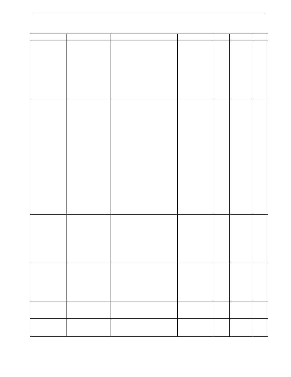
Table 1-6: MPU XRAM Locations
Name
Purpose
LSB
Default
)?
Signed?
Bits
i_min
Metering element
enters creep mode
if current is below
this value.
If 0, creep logic is
disabled. In creep
mode, on each me-
tering element, Wh,
VARh, i0sqsum,
and other items are
zeroed.
Same units as CE’s i0sqsum.
0.08A
)0
signed
32
cfg
Configure meter
operation on the fly.
bit0: 1=Display KWh.
bit1: 1=clear accumulators, er-
rors, etc. (e.g., “)1=2”)
bit2: 1=Reset demand. (e.g.,
“)1=4”)
bit3: 1=CE Raw mode. MPU
does not change CE values with
creep or small current calcula-
tions.
bit5: 1= Send a message once
per second for IEC 62056-217
Mode D on UART 1, at 2400
BAUD, even parity. The meter’s
serial number and current Wh
display are sent as data. UART
1 is routed to an IR LED if pos-
sible. Mode D data fields are
prefaced with OBIS codes in
legacy format.
7,1
bit6: 1=Auto calibration mode
1
bit7: 1=Enable Tamper Detect
2,1
0
Do nothing spe-
cial.
)1
N/A
8
v_min
error if below. Also
creep.*
Below this, low volt-
age seconds are
counted. Voltage,
Wh, VARh, Fre-
quency, and other
voltage-dependent
items are zeroed.
Same units as CE’s v0sqsum.
40V
)2
signed
32
i_max
Scaling Maximum
Amps for standard
sensor.
0.1A
110.5 for 200
μΩ shunt with
8x preamp.
884.0 A for 200
μΩ shunt,
442.0A for 400
μΩ shunt.
)3
signed
16
v_max
Scaling Maximum
Volts for PCB
0.1V
600 V, for the
6541 REV 3.0
Demo Board.
)4
signed
16
i_limit
Error if exceeded.
Same units as CE’s i0sqsum.
50.9A =
30A*sqrt(2)
*120%
)5
signed
32