2 application information, 1 sensor connections and equations, 1 sensor wiring – Maxim Integrated 71M6541 Demo Board User Manual
Page 34: Application information, Sensor connections and equations, Sensor wiring, Figure 2-1: shunt connections
71M6541 Demo Board REV 3.0 User’s Manual
34
Rev 4.0
2 APPLICATION INFORMATION
2.1 SENSOR CONNECTIONS AND EQUATIONS
The 71M6541 Demo Board supports the following meter configurations and equations:
•
Single-phase two-wire (EQU 0)
•
Single-phase three-wire (EQU 1)
Note: Support of EQU 2 requires the 71M6542 IC, which will be available on a separate Demo Board.
CAUTION: THE DIAGRAMS SHOWN IN THIS SECTION ARE SYMBOLIC AND DO
NOT REFLECT THE PHYSICAL CONNECTIONS OF THE DEMO BOARD!
THE GROUND OF THE DEMO BOARD IS AT LINE (LIVE) VOLTAGE!
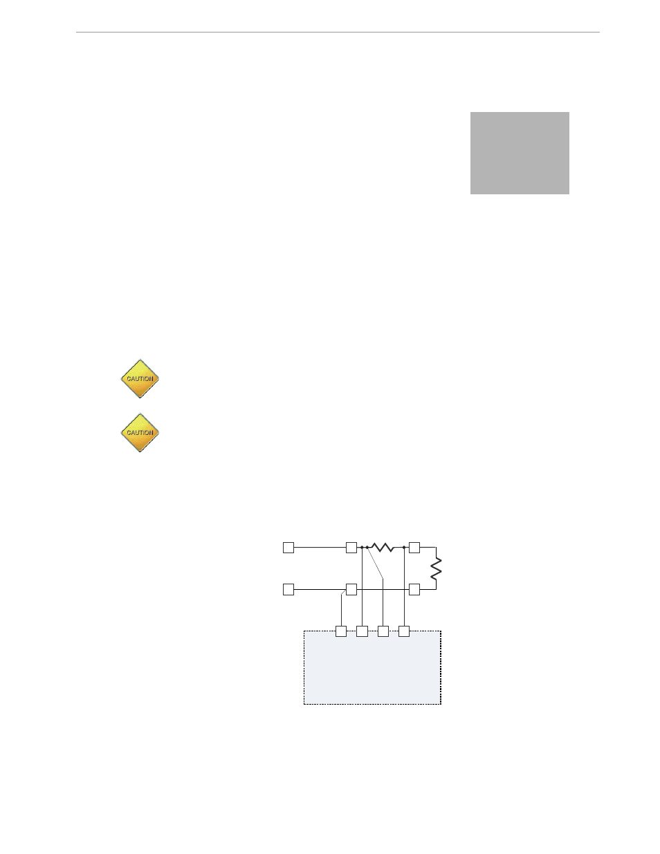
2.1.1 SENSOR WIRING
The Demo Board is referenced to LINE voltage. This means that the sensor wires have to be connected as
shown in Figure 2-1.
Figure 2-1: Shunt Connections
LOAD
LINE
Neutral
Shunt
IAP
LINE
IAN
NEUTRAL
2
- DS80C390 (58 pages)
- DS5001FP (26 pages)
- MAX1416 (14 pages)
- MAX5865 (18 pages)
- DS33Z41 (167 pages)
- MAX1202 (7 pages)
- USBTO232 (31 pages)
- HFAN-09.5.0: Pattern Creator/Converter Software (8 pages)
- MAX-IDE MAXQ Microcontrollers (11 pages)
- MAX6876 Power-Supply Tracker/Sequencer (6 pages)
- MAX6877 Power-Supply Tracker/Sequencer (3 pages)
- 78Q8430 ARM9(920T) Linux Driver Diagnostic Guide (19 pages)
- 78Q8430 Software Driver (54 pages)
- 78Q8430 ST 5100/OS-20 with NexGen TCP/IP Stack (28 pages)
- 6612_OMU_S2_URT_V1_13 (56 pages)
- 6612_OMU_S2+2_URT_V1_14 (58 pages)
- 71M6511 Power Meter IC Family Software (137 pages)
- 71M65xx ADM51 ICE Safety Notice (2 pages)
- 71M6511 2-Layer Demo Board (2 pages)
- 71M6511 4-Layer Demo Board (2 pages)
- 78Q8430 Linux Driver ARM Platform (22 pages)
- 71M6513 Demo Board (2 pages)
- 71M6521DE Energy Meter IC Family Software (138 pages)
- 71M6521 Demo Board (2 pages)
- 71M6531 Demo Board (2 pages)
- 71M6531 Energy Meter IC Family Software (116 pages)
- 71M6533 Demo Board (2 pages)
- 71M6534H Demo Board (2 pages)
- 71M6515H Demo Board (2 pages)
- 73S1209F Evaluation Board (2 pages)
- 73S12xxF (38 pages)
- 73S12xxF Software (93 pages)
- 73S1210F Evaluation Board Lite (2 pages)
- 73S1210F Evaluation Board (2 pages)
- 73S1210F Multi-SAM Evaluation Board Lite (2 pages)
- 73S12xxF USB-CCID Linux DFU Host Application (8 pages)
- 73S1215F Device Firmware Upgrade Host Driver/Application (10 pages)
- 73S12xxF USB-CCID Host GUI (22 pages)
- 73S1215F Windows XP 32 USB CCID and DFU Drivers (15 pages)
- 73S1215F CCID USB Linux Driver (16 pages)
- 73S1215F Evaluation Board (2 pages)
- 73S1215F Evaluation Board Lite (2 pages)
- 73S1217F Evaluation Board (2 pages)
- 73S1217F Evaluation Board Lite (2 pages)
- MAXQ Family (216 pages)