4 other techniques for avoiding magnetic crosstalk, Other techniques for avoiding magnetic crosstalk, Figure 2-17: loop formed by shunt and sensor wire – Maxim Integrated 71M6541 Demo Board User Manual
Page 56: Figure 2-18: shunt with compensation loop, Figure 2-19: shunt with center drill holes
71M6541 Demo Board REV 3.0 User’s Manual
56
Rev 4.0
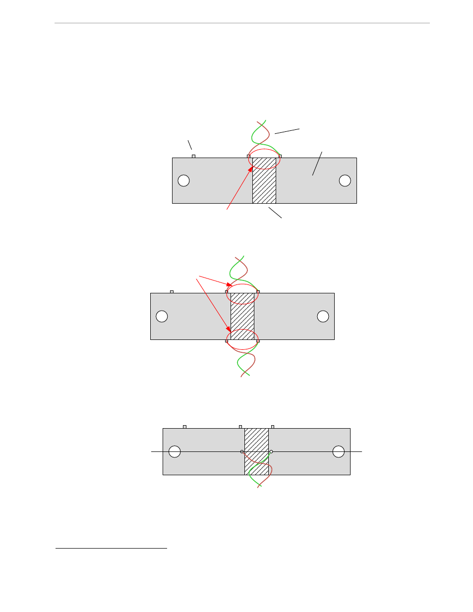
2.6.4 OTHER TECHNIQUES FOR AVOIDING MAGNETIC CROSSTALK
With very high currents or close distances between shunt sensors, magnetic pickup or cross-talk will sometimes
occur even if good placement practices are followed.
One mechanism for cross-talk is shown in Figure 2-17, where the Manganin zone and the sensor wire act as a
loop that will generate an output voltage similar to that generated by a Rogowski coil.
The effect of this loop can be compensated by adding a second loop on the opposite side of the shunt resistors,
as shown in Figure 2-18.
Figure 2-17: Loop Formed by Shunt and Sensor Wire
Figure 2-18: Shunt with Compensation Loop
Since the compensation loop is impractical, a similar compensation effect can be achieved by attaching the
sensor wires in the center, as shown in Figure 2-19. An economical approach to this technique is to drill holes in
the center of the shunt resistor for attachment of the sensor wires
.
Figure 2-19: Shunt with Center Drill Holes
1
Patent pending
Loop
Manganin
Copper
Sensor wires
Optional contact for
voltage
Symmetrical
loops