3 single-phase three-wire (equ 1), Single-phase three-wire (equ 1) – Maxim Integrated 71M6541 Demo Board User Manual
Page 36
71M6541 Demo Board REV 3.0 User’s Manual
36
Rev 4.0
in the primary channel, the CE code allows scaling between the two channels so that all energy calculations can
be based on
IMAX
.
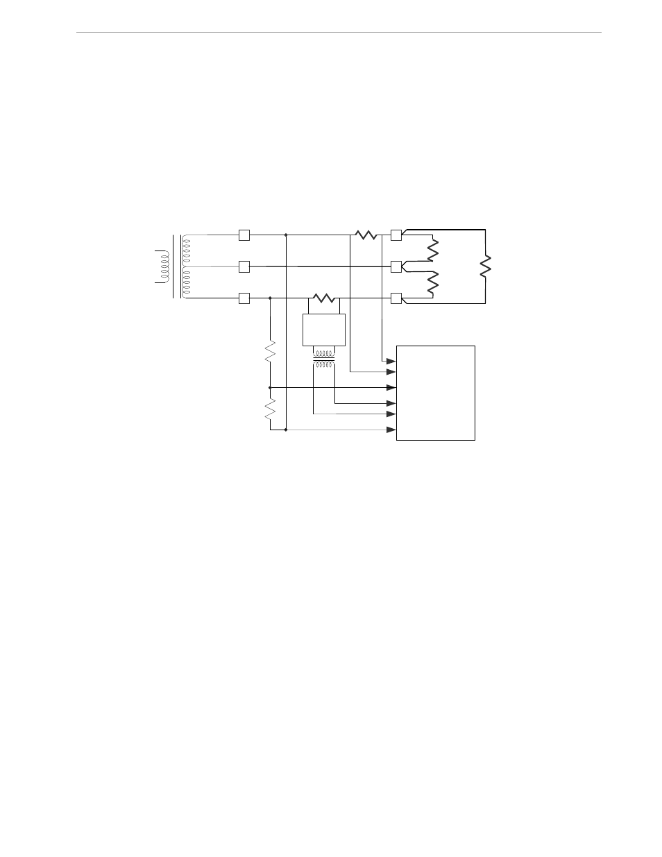
2.1.3 SINGLE-PHASE THREE-WIRE (EQU 1)
This meter configuration (see Figure 2-4) is used in North America (ANSI market) and parts of South America.
The energy measurement is based on the following equation:
P = VA/2 * (IA – IB)
Both current sensors can be shunt sensors. The second current sensor may also be a CT. The Demo Board
has provisions for connecting either sensor type, but the default configuration for the second current sensor is
the connection via on-board 71M6X0X Remote Sensor Interface.
Figure 2-4: Single-Phase Three-Wire Meter with two Shunt Sensors
By default, the gain of the amplifier for the IAP/IAN inputs is set to 1. See the explanation below Table 1-8 for
the calculation of
IMAX
.
As for the single-phase two-wire configuration, the CE code allows for scaling of differences between the cur-
rents in both phases so that all energy calculations can be based on
IMAX
.
LOAD
A
A
N
Shunt
71M65XX
IAP
V3P3A
VA
Distribution
transformer
B
LOAD
B
LOAD
IBP
Shunt
IAN
IBN
71MXXXX