Maxim Integrated 71M6541 Demo Board User Manual
Page 59
71M6541 Demo Board REV 3.0 User’s Manual
59
Rev 4.0
Item #
Reference
Designator
Name
Use
13
J21
DEBUG
Connector for Debug Board. 2x8 pin male header.
14
SW5
RESET
Chip reset switch: When the switch is pressed, the RESET
pin of the IC is pulled high which resets the IC into a known
state.
15
J12
--
2-pin header. If a jumper installed, the battery BT1 will be
connected to the V3P3SYS net.
16
J13
--
2-pin pin header. If a jumper installed, the battery BT2/BT3
will be connected to the V3P3SYS net.
17
BT3
--
Alternate footprint for BT2. A circular battery may be
mounted in this location (on the bottom of the board).
18
SW3
PB
Pushbutton connected to the PB pin on the IC. This push-
button can be used in conjunction with the Demo Code to
wake the IC from sleep mode or LCD mode to brown-out
mode.
19
JP20
5.0 VDC
Circular connector for supplying the board with DC power.
Do not exceed 5.0 VDC at this connector!
20
J7
IAP/IAN
2-pin header connected to pins IAP and IAN on the IC.
21
J6
VA
2-pin header connected to pins VA and V3P3A on the IC
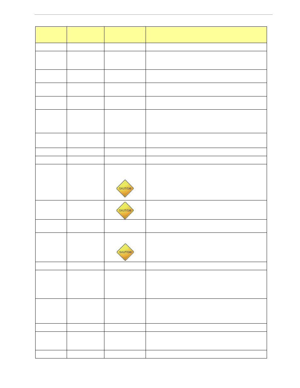
22
J3
IAN_IN, IAP_IN
2-pin header for the connection of the primary (non-
isolated) shunt. This header is on the bottom of the board.
Since the board is at line voltage, the shunt corresponding
to the line side of the meter should be connected here.
Caution: Connecting the shunt corresponding to
the neutral voltage will result in board damage!
23
JP6
A jumper is placed across JP6 to activate the internal AC
power supply.
Caution: High Voltage! Do not touch!
24
J11
NEUTRAL
The NEUTRAL voltage input connected to V3P3. This input
is a spade terminal mounted on the bottom of the board.
25
J4
LINE
LINE is the line voltage input to the board. It has a resistor
divider that leads to the pin on the IC associated with the
voltage input to the ADC. This input is a spade terminal
mounted on the bottom of the board.
Caution: High Voltage! Do not touch this pin!
26
J10
IBP, IBN
2-pin header connected to pins IBP and IBN on the IC
27
J8
--
2-pin header on the bottom of the board for optional con-
nection of a CT. When using a CT, the burden resistor lo-
cations R33/R34 have to be populated. Also, the resistors
and capacitors for filtering (R26/C25, R57/C12) and for
biasing the IBP/IBN inputs (R86, R87) must be populated.
28
J5
IBP_IN, IBN_IN
2-pin header for the connection of the secondary (remote)
shunt. This header is on the bottom of the board.
The shunt connected here should be the one correspond-
ing to the neutral side of the meter.
29
JP2
5-pin header for access to OPT_TX and OPT_RX signals.
30
JP3
ICE_E
3-pin header for the control of the ICE_E signal. A jumper
across pins 1-2 disables the ICE interface; a jumper across
pins 2-3 enables it.
31
JP7
SEGDIO51
2-pin header that allows connecting the