3 placement of sensors (iec), Placement of sensors (iec), Figure 2-16: improved sensor arrangement – Maxim Integrated 71M6541 Demo Board User Manual
Page 55
71M6541 Demo Board REV 3.0 User’s Manual
55
Rev 4.0
2.6.3 PLACEMENT OF SENSORS (IEC)
The arrangement of the current terminals in a typical IEC meter enclosure predetermines the spacing of the
shunts, and usually allows for only for 20 to 22 mm center-to-center spacing between the shunts. This means
that the clearance between adjacent shunts is typically only 10 mm or less. A typical arrangement is shown in
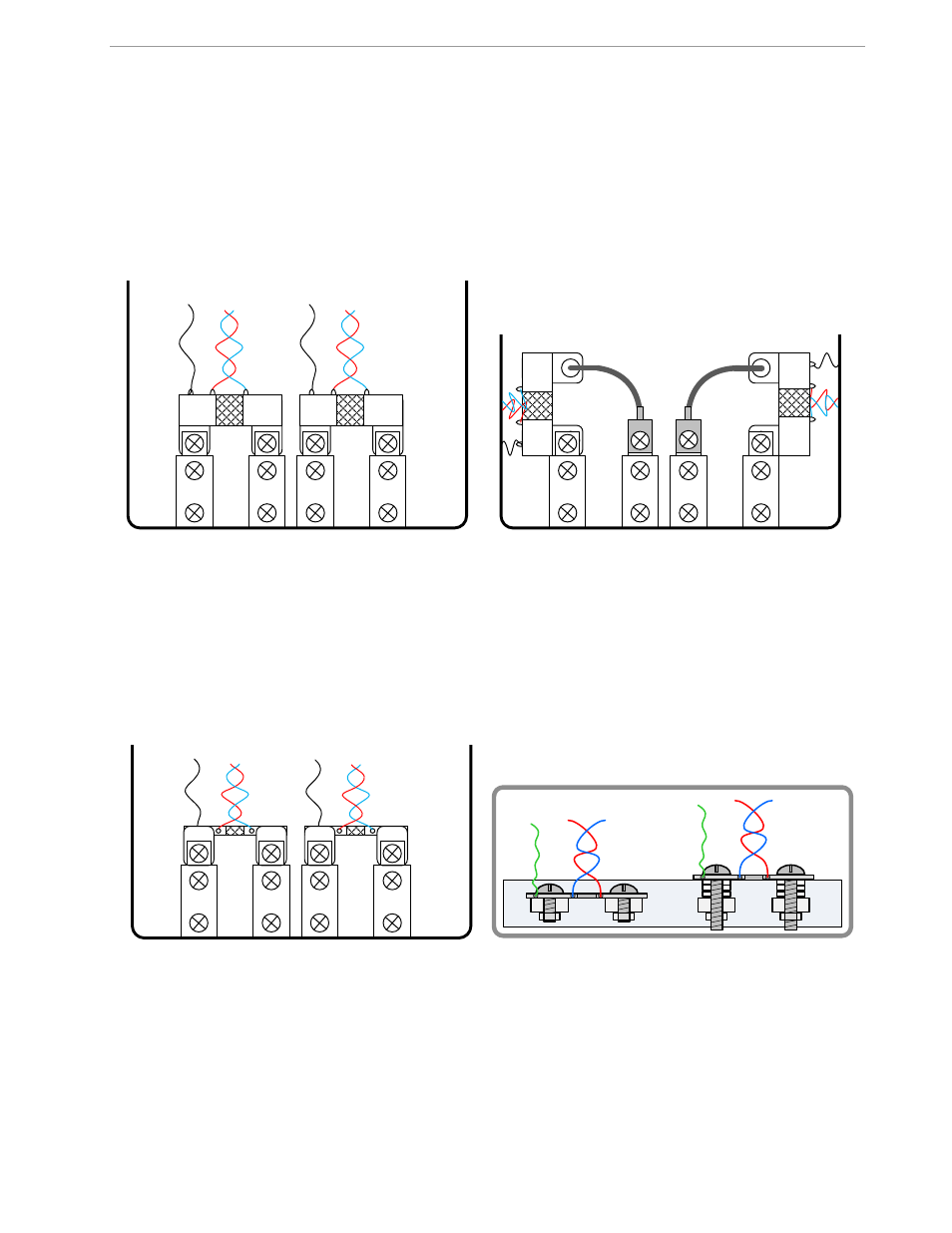
Figure 2-15, left side. This arrangement is not optimized for suppression of cross-talk.
In order to minimize cross-talk between phases, the shunts should be turned by 90 degrees as shown in Figure
2-15, right side. In this arrangement, the sensitive areas of the shunts are kept away from the adjacent currents.
Figure 2-15: Typical Sensor Arrangement (left), Recommended Arrangement (right)
Other arrangements are shown in Figure 2-16. In the left figure, the shunts are shown swiveled by 90 degrees
towards the terminals. In the right figure, the shunts are shown staggered in height, for example by using spac-
ers.
It is useful to minimize the loop area formed by the Manganin zone of the shunts and the wires. As with the AN-
SI sensors, it is recommended that sensor wires are tightly twisted to avoid loops that can be penetrated by the
magnetic fields of the sensors or conductors.
Figure 2-16: Improved Sensor Arrangement