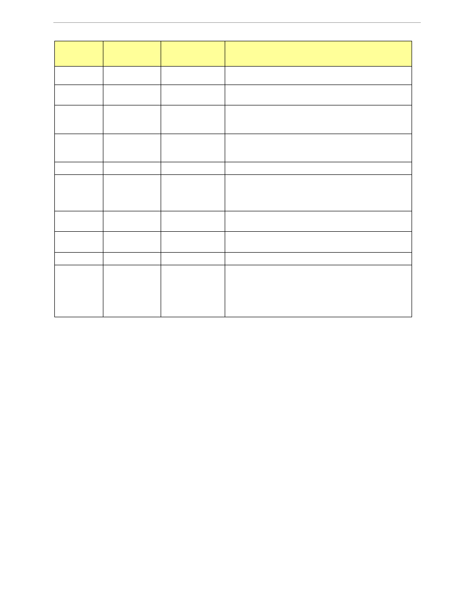
Table 3-1: 71m6541-db rev 3.0 description – Maxim Integrated 71M6541 Demo Board User Manual
Page 60
71M6541 Demo Board REV 3.0 User’s Manual
60
Rev 4.0
Item #
Reference
Designator
Name
Use
SEGDIO51/OPT_TX pin to the LCD. If the second UART is
used, the jumper should be removed from the header.
32
J14
EMULATOR I/F
2x10 emulator connector port for the Signum ICE ADM-51
or for the TFP2 Flash Programmer.
33
JP54
E_RXTX
Three 2-pin headers that connects the E_RXTX, E_RXTX,
and E_TCLK pins to the LCD. The emulator pins should be
configured as LCD pins when this jumper is inserted.
34
JP8
SEGDIO55
2-pin header that allows connecting the
SEGDIO51/OPT_RX pin to the LCD. If the second UART is
used, the jumper should be removed from the header.
35
J19
SPI
2X5 header providing access to the SPI slave interface.
36
JP9, JP10,
JP11, JP12
SPI_DO, SPI_DI,
SPI_CK,
SPI_CSZ
Four 2-pin headers that connect the SPI_DI, SPI_DO,
SPI_CK, and SPI_CSZ pins to the LCD. The SPI pins
should be configured as LCD pins when these jumpers are
inserted
37
CN1
USB PORT
This connector is an isolated USB port for serial communi-
cation with the 71M6541.
38
U8
LCD
3-row LCD with 6 7-segment digits per row and special
metering symbols.
39
JP59
VPULSE
2-pin header connected to the VARh pulse LED
40
JP5
UART_RX, ROUT
2-pin header for connection of the RX output of the isolated
USB port to the RX pin of the 71M6541. When the Demo
Board is communicating via the USB port, a jumper should
be installed on JP5. When the Demo Board is communi-
cating via the Debug Board plugged into J21, the jumper
should be removed.
Table 3-1: 71M6541-DB REV 3.0 Description