2 single-phase two-wire (equ 0), Single-phase two-wire (equ 0) – Maxim Integrated 71M6541 Demo Board User Manual
Page 35
71M6541 Demo Board REV 3.0 User’s Manual
35
Rev 4.0
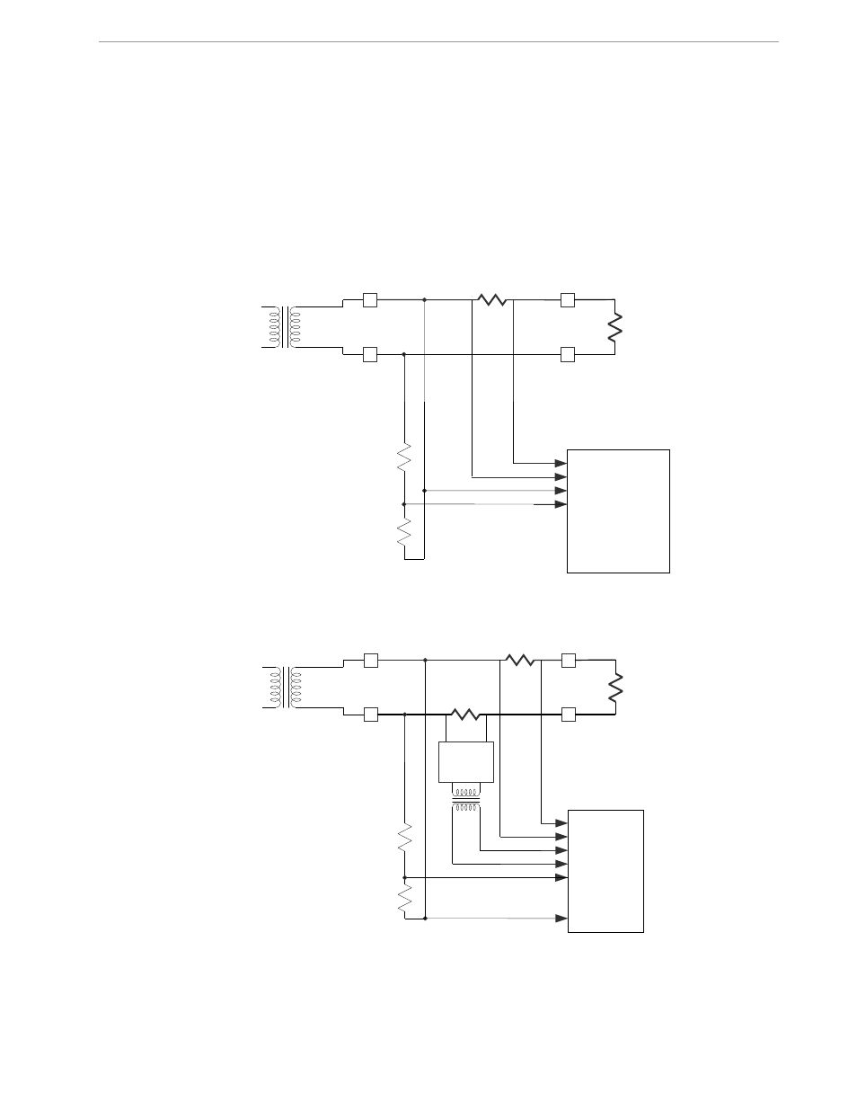
2.1.2 SINGLE-PHASE TWO-WIRE (EQU 0)
This is the most basic configuration for this Demo Board. The current sensor is connected directly to the
IAP/IAN inputs of the 71M6541 (see Figure 2-2). The energy measurement is based on the following equation:
P = VA * IA
See the explanation below Table 1-8 for the calculation of
IMAX
.
A second current sensor can be connected to the IBP/IBP inputs of the 71M6541, for example to detect tamper-
ing (see Figure 2-3). The second current sensor can be another shunt resistor that is isolated using the on-
board 71M6X0X Remote Sensor Interface. The Demo Board has provisions for connecting either a shunt or a
CT sensor, but the default configuration is the shunt sensor connected via on-board 71M6X0X Remote Sensor
Interface. See section 3.1 for details.
Figure 2-2: Single-Phase Two-Wire Meter with Shunt Sensor
Figure 2-3: Single-Phase Two-Wire Meter with two Shunt Sensors
When the Demo Code is using equation 0, the energy calculation and pulse generation is solely based on the
primary shunt (IAP/IAN). The readings from the second shunt can be obtained by the MPU in CE registers and
used for tamper detection. Since the shunt in the second current channel may be different from the shunt used
Distribution
transformer
LOAD
LINE
N
Shunt
71M6541
IAP
V3P3A
VA
IAN
LOAD
LINE
N
Shunt
71M6541
IAP
V3P3A
VA
IAN
Shunt
IBP
IBN
71M6XXX