Ptz control and color setup, 1 cable connection, 2 ptz setup – IC Realtime 4/8 All Channel 720P Mini 1U HD-AVS DVR User Manual
Page 47: 8 ptz control and color setup
38
4.8 PTZ Control and Color Setup
Note: All the operations here are based on PELCOD protocol. For other protocols, there might be a
little difference.
4.8.1 Cable Connection
Please follow the procedures below to go on cable connection
Connect the dome RS485 port to DVR 485 port.
Connect dome video output cable to DVR video input port.
Connect power adapter to the dome.
4.8.2 PTZ Setup
Note: The camera video should be in the current screen. Before setup, please check the following
connections are right:
PTZ and decoder connection is right. Decoder address setup is right.
Decoder A (B) line connects with DVR A (B) line.
Boot up the DVR, input user name and password.
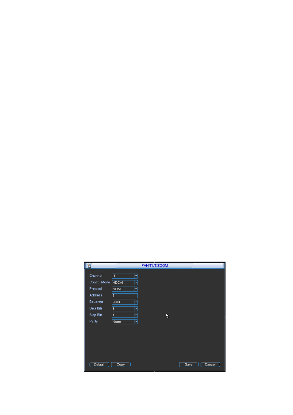
In the main menu, click setting, and then click Pan/Tilt Control button. The interface is shown as in
Figure 4-34. Here you can set the following items:
Channel: Select the current camera channel.
Control mode: You can select control mode from the dropdown list. There arw two options:
Serial/HD-AVS. For HD-AVS series product, please select HD-AVS. The control signal is sent to the
PTZ via the coaxial cable. For the serial mode, the control signal is sent to the PTZ via the RS485
port.
Protocol: Select corresponding PTZ protocol.
Address: Default address is 1.
Baud rate: Select corresponding baud rate. Default value is 9600.
Data bits: Select corresponding data bits. Default value is 8.
Stop bits: Select corresponding stop bits. Default value is 1.
Parity: There are three options: odd/even/none. Default setup is none.
Figure 4-34