Master fader Page 18: Digital output
Page 18: Digital output
Attention! The text in this document has been recognized automatically. To view the original document, you can use the "Original mode".
3. Signal flow and mode
Master fader
This adjusts the master L/R level.
Meters
Ch Meter in METERS mode indicates the level of the signal after the fader and muting. Bus Meter
in METER mode indicates the level of the signal of each bus after the volume and muting. The
levels are expressed as the remaining margin until the internal digital signal would peak (begin to
distort).
The master L/R signals are indicated by the master level meter located on the front panel. The
meter calibration indicates the output level from the analog outputs.
Analog output
MASTER OUT (L/R) jacks, MON OUT (L/R) jacks, headphone (L/R) jack, and AUX SEND (1,2)
jacks are provided. The two EFF SEND (1, 2) systems are dedicated to the internal digital effect
processors. For each channel, AUX SEND and EFF SEND can be switched between pre/post, and
turned on/off.
Digital output
This section provides adat OPTICAL OUT A (1-8), B (1-8), and S/P DIF MASTER OUT jacks, adat
OPTICAL OUT A (1-8) always outputs group buses 1~8. adat OPTICAL OUT B (1-8) provides
patching capability. These settings are made in Ex.BUS 10 mode. When cascading two or more
168RC units, connect the buses using the B connectors. S/P DIF MASTER OUT outputs the same
signal as the MASTER OUT (L/R).
168RC Virtual Console Surface
A B C D ° E ° ° F G H 1 2 3 4"°5 4 7 8
1 2 3 T'°5° 6 7 8
Input Motrix
il/S/P]or[INPLrri
lEx-BUSIOl
Solo AUX Eff Master
Ch
1
2 3 4
5 6 7 8
9 10 11 12 13 14 15 16 Group Bus 1
2
3
4
5
6
7
8
L
R
1
2
1
2
L
R
Group AAoster
[BUS MASTER]
1
2
3
4
5
6
7
8
^
pan
O
o
o
o
o
o
o
o
o o o o o o o o
Send Master
[SND A4ASTER]
AUX1 AUX2
Effi Eff2
O O
O O
ON
CD
CD
CD CD
SOLO MODE
Exclusive
MON-»
CD
iMisci
I
I
ISNO MASTERl
Master AUX1 AUX2 Effi Eff2
□ □□
CJCD
TAPE/MONITOR MOtmSRlEVa
a - T - o
Stereo Group
□
motes Lfva
□
□
□
Gl G2 G3
□
□
G4 G5
□
□
□
G6 G7 G8
-------- Vdue -
o o -
.....I—I I I Moster
--------- Vc*J» •
o o -
-------- BtWSS ---------Out -
.....□ Master
[Eff2l
ItejTl
r~p
Master L/R
[ ] :Mode Name
Moster L/R
AUX 1/2
Moi^r L/R
Group Bus
© 1
© 2
©
3
® 4
©
5
©
4
© 7
Bus Assignable
I
©
2
©
3
©
4
©
5
©
4
©
7
©
8
OUIPUT
I
ea
.
bus
roi
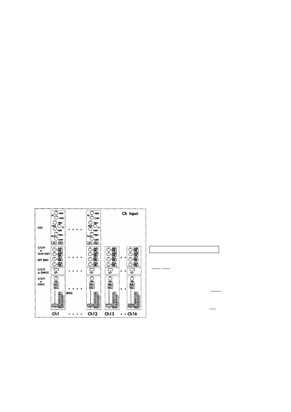
This diagram shows how the 168RC would be laid out if it were an analog mixer. [
corresponding mode name.
] indicates the
1 1