English, Warning, Caution – KEYENCE SL-CHG Series User Manual
Page 40
Chapter 3 Wiring
3-6
3
English
ENGLISH
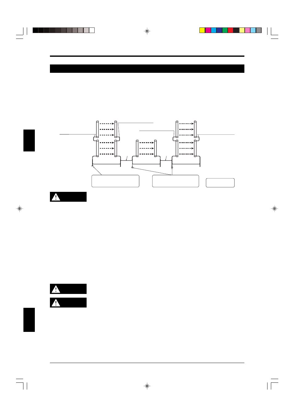
3-7 Series Connectin and Light Interference Prevention Connection (Parallel Connection)
The series and parallel light interference prevention connection can be combined as shown below.
This function is valid if the number of SL-CHG in a series connection and connected via a light interfer-
ence prevention cable is 12 or less, and if the total number of beam axes is 192 or less. For SL-CHG
units that are configured as main units, the total number of SL-CHG Series connected in series must
be 4 pairs or less, while the total number of SL-CHG Series connected in series and configured as sub
units must be 3 pairs or less. The response time of the SL-CHG is not affected by this combination of
series connections and light interference prevention connections.
See “Connection for Light Interfer-
ence Prevention” (page 3-5).
Main/sub select input: Sub unit is
selected by +24 V input voltage
or open connection (pink wire)
Main/sub select input: Main unit
is selected by the input level of
0V connection (pink wire)
SL-S1/S3G Series connection
cable for transmitter (gray)
SL-S1/S3G Series connection
cable for receiver (black)
SL-S1/S3G Series connection
cable for transmitter (gray)
SL-S1/S3G Series connection
cable for receiver (black)
Output
Output
Output
Main unit (4pairs Max.)
Synchronization
cable
(Orange)
(Orange/Black)
Synchronization
cable
(Orange)
(Orange/Black)
Synchronization
cable
(Orange)
(Orange/Black)
Light inter-
ference pre-
vention cable
(gray)
(gray/black)
Light inter-
ference pre-
vention cable
(gray)
(gray/black)
Sub unit (3pairs Max.)
Sub unit (3pairs Max.)
Tr
ansmitter
Tr
ansmitter
Receiv
er
Receiv
er
Tr
ansmitter
Tr
ansmitter
Receiv
er
Receiv
er
Tr
ansmitter
Receiv
er
The total number of
beam axes is 192.
WARNING
• Use the series connection cables provided by KEYENCE only (
See 1-2-2 “Ca-
bles” (
➮ page 1-3) for special cable types and relevant information). Otherwise,
the SL-CHG may not operate normally and a serious harm, such as an injury or
death of a machine operator, may result.
• Use 2-wire shielded cable that is at least AWG #22 (nominal cross-sectional area
of 0.3 mm
2
) for interference prevention connections. Also, use shielding that has
the same electric potential as that being used for the SL-CHG itself. Otherwise,
the SL-CHGs may not operate normally and a serious harm, such as an injury or
death of machine operator, may result.
• When using 2 or more of SL-CHG units without using the above-mentioned
series connection, a light interference prevention connection, or a combination of
both, install the SL-CHGs correctly to prevent light interference.
➮See “2-4-5
Light Interference Prevention Method” (
➮ page 2-15).
The responsible personnel shall perform an operational check after the SL-CHG
has been installed to ensure the absence of light interference.
If the SL-CHG units are not connected in accordance with the provisions in this
instruction manual, the SL-CHG will not operate normally without light interfer-
ence, which could result in serious harm, including serious injury or death to the
machine operator.
CAUTION
The NPN output cable and PNP output cable cannot be used simultaneously.
WARNING
Always use the cable for PNP or NPN output suitable for the machine's safety
system with which the SL-CHG is installed. If the output type does not match the
specifications of machine's safety system, it is not possible to stop the machine and
serious harm, such as an injury or death of a machine operator, may result.