3 specifications, English, English 1-3 specifications – KEYENCE SL-CHG Series User Manual
Page 12
Chapter 1 Overview and Specifications
1-4
1
English
ENGLISH
1-3 Specifications
SL-CHG specifications by model
Environ-
mental
specifica-
tions
Material
Approved
standards
Detection zone
No. of beam axes
Beam axis interval/lens diameter
Operating distance
Detection capability
Effective Aperture Angle
Response time
Light source
Operation form
Rating
Power voltage
Output type
Max. load current
OFF-state voltage
Protective structure
Ambient temperature
Storage ambient temperature
Relative humidity
Storage ambient humidity
Vibration
Shock
Main unit case
Upper case/Lower case
Overlay
EMC
EMS
EMI
Safety
OSSD
Output
Model
IP65 (IEC60529)
-10
°C to 55°C (No frost)
-10
°C to 60°C (No frost)
35 % to 85 %RH (No condensation)
35 % to 95 %
Ambient light
White incandescent lamp: 5,000rx or less Sunlight: 20,000rx or less
10 to 55 Hz, 0.7 mm compound amplitude, 20 sweeps each in X, Y, and Z directions
100 m/s
2
(Approx. 10G) 16ms pulse, in X, Y, Z directions 1,000 times each axis
Aluminum
Zinc die-cast
Polycarbonate
IEC61496-1, EN61496-1, UL61496-1
EN55011 Class A, FCC Part15 Class A
IEC61496-1, EN61496-1, UL61496-1 (
type
4 ESPE)
IEC61496-2, EN61496-2, UL61496-2 (
type
4 AOPD)
UL508
140 mm to 1,260 mm (5.51" to 49.61")
8 to 64 beam axes
20 mm / ø5.0 mm (0.79" / ø0.2")
0.3 m to 9 m (11.81" to 29.53 ft.)
ø25 mm(0.98") (when blanking function is not used)
Max.
±2.5° (When operating distance is at least 3m (9.84 ft.))
15 ms*
1
Infrared LED (850 nm)
Turns on when light is received from all light beams (except when the blanking function is used)
24V DC
±10% (Ripple P-P 10% or less)
2 outputs each for PNP and NPN, Can be changed using the connector cable
300 mA*
2
2.5 V (with a cable length of 7 m (22.97 ft.))
Max. 100
µA*
3
0.47
µF (with a load resistance of 100 Ω)
Max. 2.5
Ω*
4
SL-CHG Series
No. of beam axes
Beam axis interval
Detection zone
Current
consump-
tion
Weight
20 mm (0.79")
Model
8
140 mm (5.51")
55 mA
67 mA
Approx. 165 g
Approx. 180 g
SL-C08HG
Approx. 210 g
Approx. 230 g
12
220 mm (8.66")
58 mA
69 mA
SL-C12HG
Approx. 255 g
Approx. 280 g
16
300 mm (11.81")
61 mA
71 mA
SL-C16HG
Approx. 300 g
Approx. 330 g
20
380 mm (14.96")
62 mA
73 mA
SL-C20HG
Approx. 345 g
Approx. 380 g
24
460 mm (18.11")
68 mA
76 mA
SL-C24HG
Approx. 390 g
Approx. 430 g
28
540 mm (21.26")
71 mA
78 mA
SL-C28HG
Approx. 435 g
Approx. 480 g
32
620 mm (24.41")
74 mA
81 mA
SL-C32HG
77 mA
Approx. 480 g
Approx. 530 g
36
700 mm (27.56")
83 mA
SL-C36HG
Transmitter
Receiver
Transmitter
Receiver
No. of beam axes
Beam axis interval
Detection zone
Current
consump-
tion
Weight
Model
Approx. 525 g
Approx. 575 g
40
780 mm (30.71")
81 mA
86 mA
SL-C40HG
Approx. 570 g
Approx. 625 g
44
860 mm (33.86")
84 mA
88 mA
SL-C44HG
Approx. 615 g
Approx. 675 g
48
940 mm (37.01")
87 mA
90 mA
SL-C48HG
20 mm (0.79")
Approx. 660 g
Approx. 725 g
52
1020 mm (40.16")
91 mA
93 mA
SL-C52HG
Approx. 705 g
Approx. 775 g
56
1100 mm (43.31")
94 mA
95 mA
SL-C56HG
Approx. 750 g
Approx. 825 g
60
1180 mm (46.46")
97 mA
97 mA
SL-C60HG
Approx. 860 g
Approx. 945 g
64
1260 mm (49.61")
100 mA
100 mA
SL-C64HG
Transmitter
Receiver
Transmitter
Receiver
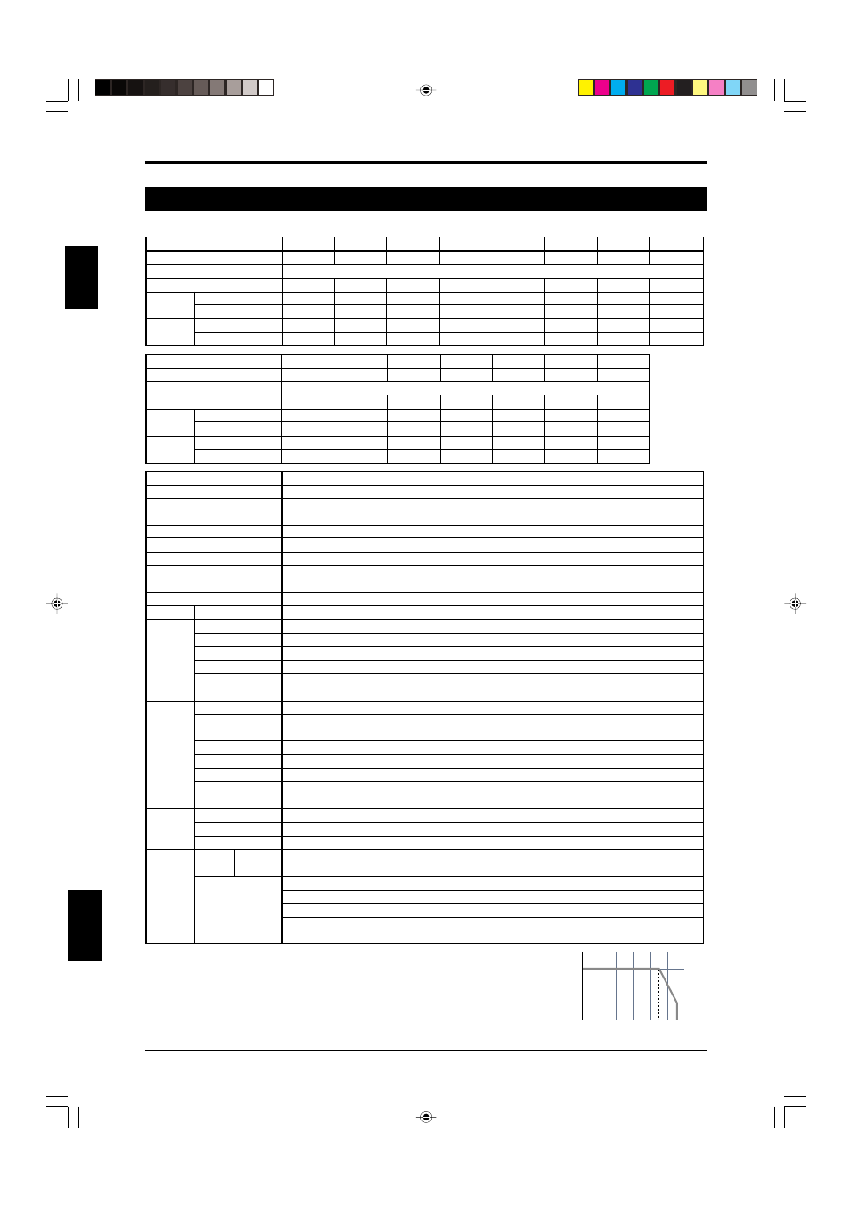
0
100
200
300
(mA)
10
20
30
40
50
(
°C)
Leakage current
Max. capacitive load
Load wiring resistance
*1 OFF
➝ ON return time is 125 ms.
*2 Note the derating illustrated in the graph to the right when using PNP output.
*3 Includes when the SL-CHG Series power supply is OFF or when there is a disconnection in the power
supply line.
*4 In order to guarantee the proper operation of the SL-CHG safety circuit, the wiring resistance
(excluding dedicated cable wiring resistance) of the cabling connected to the hardware to which the
OSSD output and OSSD input are connected must be 2.5
Ω or less. For NPN output type cable, do not
let wiring resistance exceed a maximum of 1.0
Ω when the cable length is 15 m (49.21 ft.) or greater
and the load current is 200 mA or higher.
“Structural Standards for Press Machinery and Shear Safety Devices” (Japanese Ministry
of Health, Labor, and Welfare Notification No. 102, issued September 21, 1978)