4 for sl-pc cable (main unit plug - m12 connector), 5 series connection, English – KEYENCE SL-CHG Series User Manual
Page 38: Warning
Chapter 3 Wiring
3-4
3
English
ENGLISH
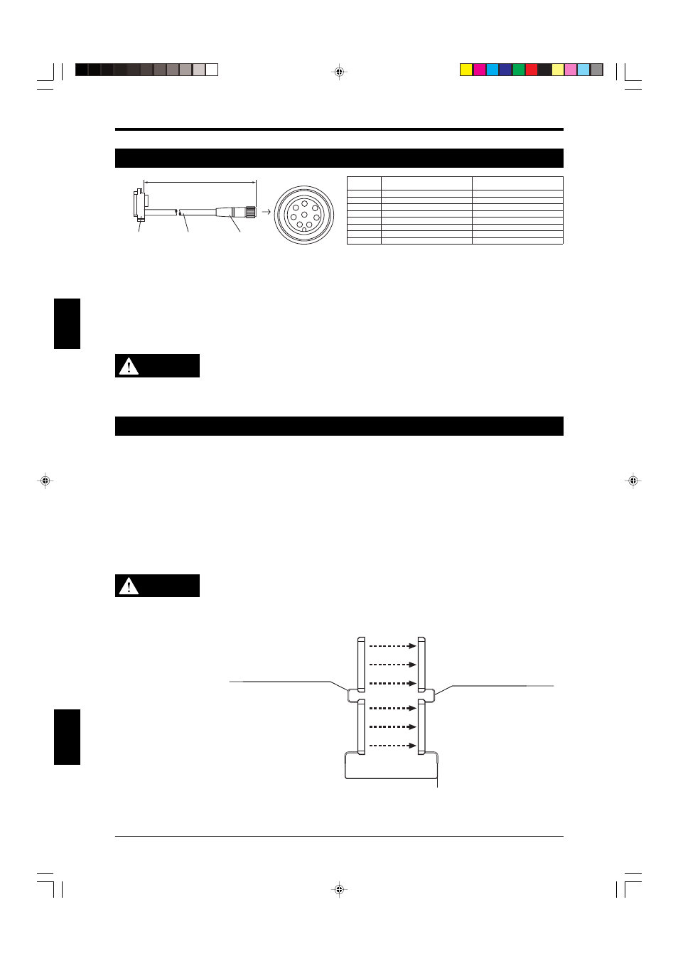
3-4 For SL-PC Cable (main unit plug - M12 connector)
8
5
6
7
1
2
3
4
Main unit
connector
2. Cable
3. M12 connector
3. M12 connector
1. Cable length
Transmitter
Main/sub select input
+24 V
Test input
Light interference prevention input (+)
RS-485 (A)
RS-485 (B)
0 V
Light interference prevention input (–)
Receiver
OSSD2
+24 V
OSSD1
Light interference prevention output (+)
RS-485 (A)
RS-485 (B)
0 V
Light interference prevention output (–)
Terminal No.
of connector
1
2
3
4
5
6
7
8
1. Cable length
SL-PC5PG 5m (16.4 ft.)
SL-PC5NG 5m (16.4 ft.) (Cannot be used for establishing a connection with the SL-R11G.)
SL-PC10PG 10m (32.81 ft.)
2. Cable color
Transmitter: gray
Receiver: black
3. M12 connector
WARNING
Limit the length of transmitter and receiver cables to 30 meters (1181.1") or less. If
the cable length exceeds the limit, the SL-CHG may not operate normally and a
serious accident, such as an injury or death of a machine operator, may result. In
addition, when bent or flexed, these cables should be allowed a minimum bend
radius of 5 mm (0.2").
3-5 Series Connection
2 or more sets of the SL-CHG can be connected by using a pair of dedicated series connection cables to
form a light curtain with a single set of output logic for press/shearing machines.
If any beam axis of any series-connected SL-CHG unit is blocked, the OSSD output (or FSD output) is
turned OFF and the machine can be stopped.
This function is valid only when the number of SL-CHG connected in series is 4 pairs or less and the total
number of SL-CHG beam axes is 192 or less. The response time of the SL-CHG Series is not affected by
the series connection.
Use the series connection cables (SL-S1 or SL-S3G).
• SL-S1: Cable length 0.15 m (5.91")
• SL-S3G: Cable length 3 m (9.84 ft.)
When installing a series connection cable, remove the top edge connector cover, and then install the cable.
WARNING
Use only the series connection cables provided by KEYENCE (
See 1-2-2 “Cables”
(
➮ page 1-3) for special cable types and relevant information). Otherwise, the SL-
CHG may not operate normally and serious harm, such as an injury or death of the
machine operator, may result. Synchronization cables must be shielded cables.
Failure to use shielded cable may result in significant harm the machine operator,
including serious injury or death.
SL-S1/S3G Series connection
cable for transmitter (gray)
SL-S1/S3G Series connection
cable for receiver (black)
Tr
ansmitter
Receiv
er
Tr
ansmitter
Receiv
er
Synchronization cable
(Orange)
(Orange/black)
Output
Unit 2
Unit 1
For connections of the transmitter and receiver of Unit 1,
refer to 3-3 “When Only
the SL-CHG is Used” (
➮ page 3-3) .