3-2 fixing the mounting brackets, English – KEYENCE SL-CHG Series User Manual
Page 28
Chapter 2 Installation and Assembly
2-10
2
English
ENGLISH
2-3-2 Fixing the Mounting Brackets
WARNING
The installation holes for screws on mounting brackets for the SL-CHG are slot-
shaped so that they are larger than the actual screw size with which they are
intended to be used. This additional space can be used to adjust the position in
which the device is installed. For this reason, the proper installation of the device
should be verified according to the procedure outlined in “4-2 Maintenance (
➮ page
4-3)” in the event that maintenance requires the removal of the device from its
target equipment or the adjustment of its installation position after its initial installa-
tion onto that target equipment. Failure to follow these installation procedures may
result in significant harm to machine operators, including serious injury or death.
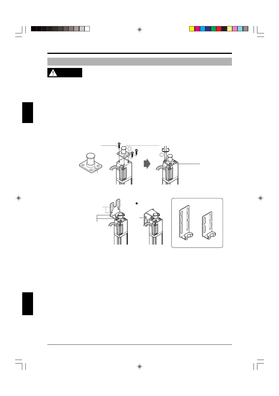
This section explains how to attach the SL-CHG mounting brackets.
1. Normal mounting bracket A (OP-42347)/B (OP-42348)/C (OP-42349) assembly and installation
Install the base mounting bracket D as illustrated below and secure it in place with the three included
screws.
Be sure to install the bracket so that the mark faces in the same direction as the transmitting or receiv-
ing surface.
Base mounting bracket D
Stamped mark
M3 (r=7)
Stamped
mark
2
1
Secure a compatible mounting bracket to the base mounting bracket D.
There are three types of compatible mounting brackets to be used depending on the mounting condi-
tions.
Screw
mounting holes
* Other types of compatible mounting bracket
(They can be mounted in the same way).
Only normal mounting bracket
A can be used facing down.
(For normal mounting bracket A)
(Normal mounting
bracket C)
(Normal mounting
bracket B)
Screw
mounting
holes
The sensor can be rotated to the
left and right when these 2 screws
(M3:R=7) are loosened, allowing
adjustment of the beam axis. (Use
a recommended tightening torque
of 0.7 N•m for these screws. When
the protect bar is in use, 0.9N•m.)