3-3 protection bar installation, English – KEYENCE SL-CHG Series User Manual
Page 30
Chapter 2 Installation and Assembly
2-12
2
English
ENGLISH
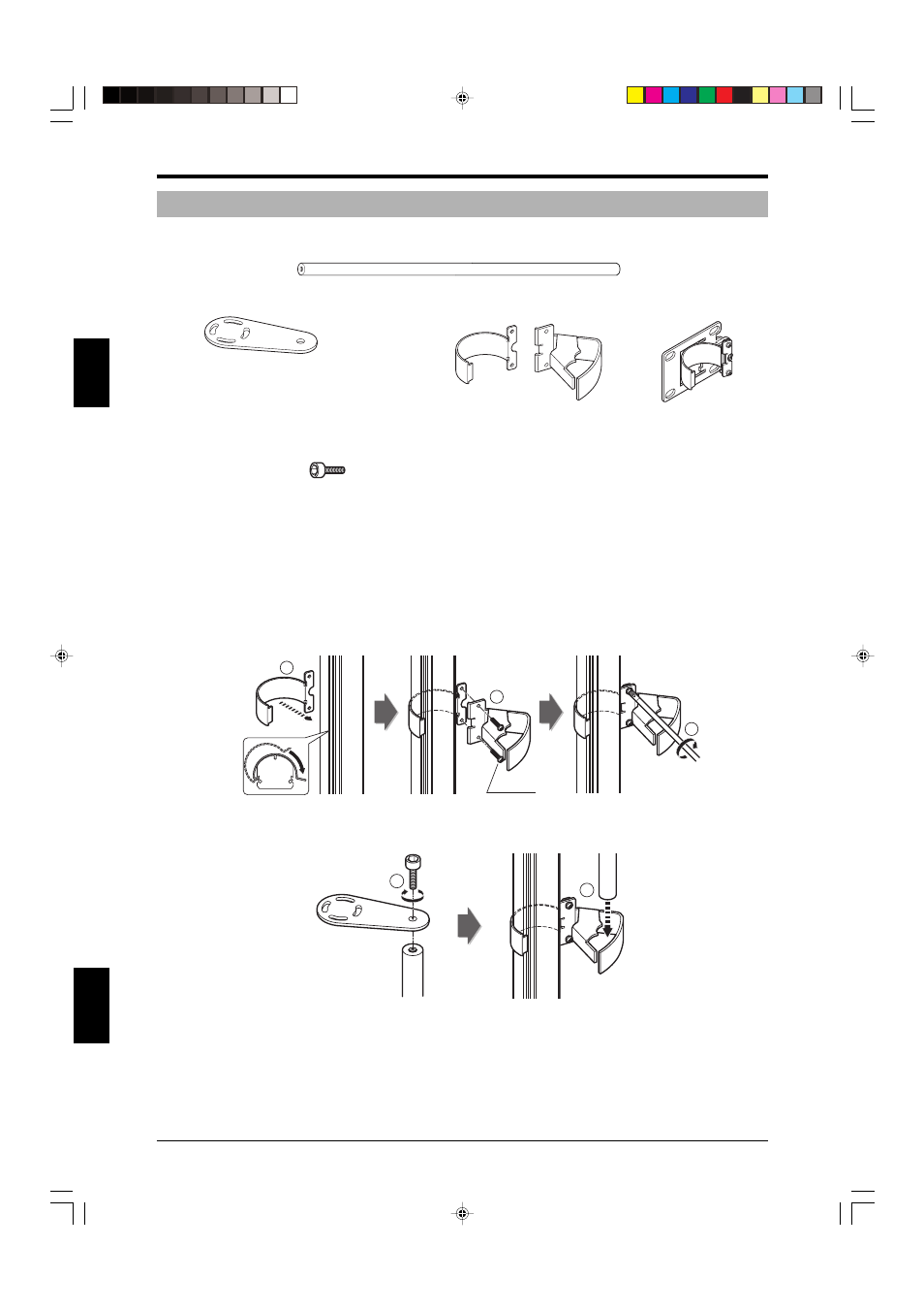
2-3-3 Protection Bar Installation
This section describes the procedure used to install the protection bar.
1. Part names
• Bar
1 bar
• Bar bracket A
A mounting torque of 0.7 N•m or less should be used when attaching brackets to the SL-CHG (M3
screws).
The bar mounting torque should be 7 N•m or less (5 mm (0.2") diagonal M6 hexagonal bolts).
2. Installation procedure
1. Install the protection bar as described in steps
➀ to ➁.
2. Install protection bars in 2 locations for models with 28 or more beam axes (SL-C28HG). See “1-4
Dimensional drawings (Dimensions by model) (
➮ page 1-7)” for information about the positions
where protection bars should be installed.
1
2
3
M3(r=7)
Recommended tightening
torque: 7 N•m
3.
1. Tighten the bolt with the hexagon socket enough to hold them in place.
2. Attach the bar to the bar support brackets.
[Top]
1
2
• Intermediate support
bracket
Bolt with hexagon socket
(Diagonally: 5mm (0.2"))
2 bolts
2 brackets for the 28 beam
axis type (SL-C28HG) only
• Screws
M3 X L7 6 screws
M3 X L10 6 screws
2 brackets
• Bar support bracket
1 bracket for installa-
tions with 36 or more
beam axes type (SL-
C36HG) only