English – KEYENCE SL-CHG Series User Manual
Page 29
Chapter 2 Installation and Assembly
2-11
2
ENGLISH
2.
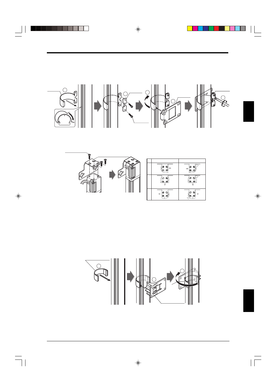
E-to-E mounting bracket (OP-42370) assembly and tightenig methods
1. Mount bracket A on the SL-CHG (Use a recommended tightening torque of 0.7 N•m).
2. Fix bracket B to bracket A using two screws (Use a recommended tightening torque of 0.7 N•m).
3. At the opposite side of bracket A from the side where bracket B is mounted, slide in bracket C,
determine its angle, and fix it using a screw (Use a recommended tightening torque of 0.7 N•m).
2
1
5
3
4
Mounting
bracket B
Mounting
bracket A
Mounting
bracket C
M3(r=7)
M4(r=12)
3. L-shaped mounting bracket (OP-42371) assembly and mounting methods
Secure the L-shaped mounting bracket using three screws as shown below.
M3 flathead
(small head) (r=5)
L-shaped mounting bracket
Installation examples of L-shaped mounting bracket
Top
Bottom
3
2
1
Beam axis surface
Beam axis
surface
Beam axis
surface
Beam axis
surface
Beam axis
surface
Beam axis surface
4. Intermediate support bracket (OP-42373) mounting method
To prevent a malfunction of SL-C32HG to SL-C64HG due to vibration, mount an intermediate support
bracket in one or two intermediate positions as appropriate. Mount the bracket correctly by following
the instructions below. For information regarding the mounting position,
➮ see the “1-4 Dimensional
Drawings” (page 1-5).
1. Mount the intermediate support bracket A on the SL-CHG.
2. Slide the intermediate support bracket B onto the intermediate support bracket A, and determine its
mounting position.
3. Attach intermediate support bracket B using four screws.
1
2
3
Intermediate
support bracket A
Intermediate
support bracket B