English – KEYENCE SL-CHG Series User Manual
Page 23
Chapter 2 Installation and Assembly
2-5
2
ENGLISH
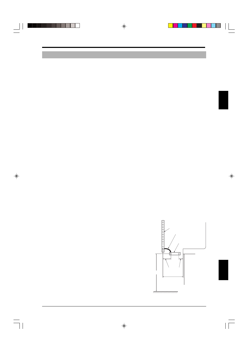
Primary beam axes
Supplementary
beam axes
Bolster
200 mm
(7.87")
or less
200 mm
(7.87")
or less
Chest-high
Sufficient length
to allow operator
to reach machine
Serial connection cable
2-2-1 Structural Standards for Power Press Machinery (Japan only)
1. The safety distance formula (reference)
The safety distance formula described in the “Structural Standards for Power Press Machinery” (Japa-
nese Ministry of Health, Labor, and Welfare Notification No. 116, issued December 26, 1977) based on
the provisions of Article 42 of the Industrial Safety and Health Law is noted below for your reference.
Use the following values as reference values to guide your calculations. When installing safety light
curtain on press machinery, be sure to do so in accordance with the provisions of the “Structural
Standards for Power Press Machinery”.
Formula (From Article 50 of the “Structural Standards for Power Press Machinery”)
D = 1.6 X (TR+ Ts)
In this formula, D, TR, and Ts represent the values described below.
D = The distance between the beam axes of safety light curtain and the hazard boundary (hazard)
(mm)
TR= The time from when the light beam is blocked to when the press machinery's emergency stop
mechanism operates (the response time of the SL-CHG Series) (15 ms)
Ts = The time from when the press machinery's emergency stop mechanism starts operating to when
the slide stops (ms)
The formula is used to calculate the safety distance (D), from which the installation distance (A) is
determined. You will need to install either supplementary beam axes or a additional safeguard when
the horizontal distance between the beam axes and the forward surface of the bolster exceeds 400
mm (15.75"), or when this distance is less than 400 mm (15.75") but the configuration is such that an
operator could fit between the beam axes and the forward surface of the bolster. (
➮See “2. How to
install supplementary beam axes” on page 2-7.)
Example
Calculating the safety distance
Assuming the maximum stop time of the press is 180 ms,
D = 1.6 X (180 + 15)
= 312 mm (12.28")
Accordingly, the safety distance for these conditions is D = 312 mm (12.28").
2. How to install supplementary beam axes
It is recommended that the SL-CHG Series units being used as supplementary beam axes be con-
nected in series to the SL-CHG Series units being used as primary beam axes. When the units are
connected in series, light interference between the units can be prevented. (
➮See “3-5 Series Connec-
tion” on page 3-4.)
1. When installing supplementary beam axes on power press
machinery where the distance between the primary beam
axes of safety light curtain installed to secure the safety
distance and the forward surface of the bolster is such that
an operator could pass through it, position the supplemen-
tary beam axes so that the horizontal distance between the
primary and supplementary beam axes is 200 mm (7.87")or
less and the horizontal distance between the bolster and the
supplementary beam axis closest to the bolster is 200 mm
(7.87") or less.
2. Supplementary beam axes should be positioned so that they
are roughly parallel to the forward surface of the bolster and
so that they are about chest-high for operators.