4 dimensional drawings, English 1-4 dimensional drawings, Chapter 1 overview and specifications – KEYENCE SL-CHG Series User Manual
Page 13
Chapter 1 Overview and Specifications
1-5
1
ENGLISH
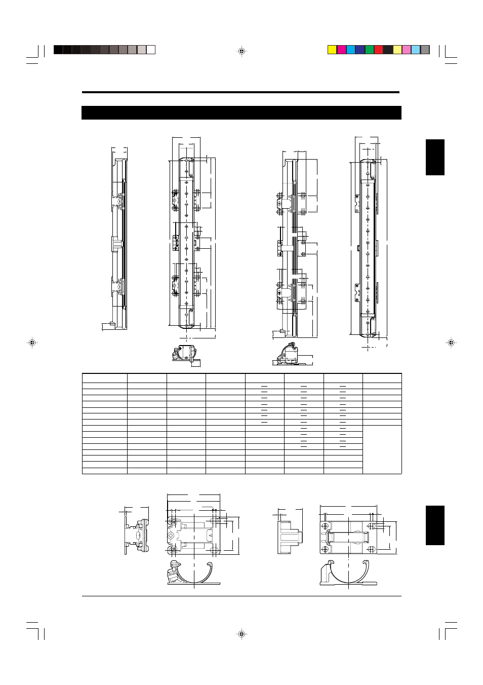
1-4 Dimensional Drawings
3
36
3
4
50
(50.4)
5
28
36
1.5
(24)
2.5
(21.2)
1
38.5
2
3.5
49
4.5
20
28
Model
16
20
24
28
No. of beam axes
8
12
40
44
48
52
32
36
56
60
64
310 (12.20")
390 (15.35")
470 (18.50")
550 (21.65")
Sensor length A
150 (5.91")
230 (9.06")
790 (31.10")
870 (34.25")
950 (37.40")
1030 (40.55")
630 (24.80")
710 (27.95")
1110 (43.70")
1190 (46.85")
1270 (50.00")
300 (11.81")
380 (14.96")
460 (18.11")
540 (21.56")
Detection zone B
140 (5.51")
220 (6.66")
780 (30.71")
860 (33.86")
940 (37.01")
1020 (40.16")
620 (24.41")
700 (27.56")
1100 (43.31")
1180 (46.46")
1260 (49.61")
385
±80 (15.16"±3.15")
425
±80 (16.73"±3.15")
465
±80 (18.31"±3.15")
505
±80 (19.88"±3.15")
345
±80 (13.58"±3.15")
545
±80 (21.46"±3.15")
585
±80 (23.03"±3.15")
625
±80 (24.61"±3.15")
333
±80 (13.11"±3.15")
360
±80 (14.17"±3.15")
387
±80 (15.24"±3.15")
413
±80 (16.26"±3.15")
Intermediate support
bracket position C*
Intermediate support
bracket position C1*
Intermediate support
bracket position C2*
677
±80 (26.65"±3.15")
730
±80 (28.74"±3.15")
783
±80 (30.83"±3.15")
837
±80 (32.95"±3.15")
43 to 89 (1.69" to 3.50")
43 to 116 (1.69" to 4.57")
43 (1.69")
43 to 63 (1.69" to 2.48")
43 to 143 (1.69" to 5.63")
43 to 169 (1.69" to 6.65")
43 to 196 (1.69" to 7.72")
43 to 197 (1.69" to 7.76")
D
With the E-to-E mounting bracket (OP-42370) installed
(Unit:mm)
Dimensions by model
E-to-E mounting bracket
(OP-42370)
Intermediate support brackets (OP-42373)
10.6
26.4
27.9
15.5
28
50.4
5
D
28
20
3.5
2
10.5
1
38.5
5
3
4
11
3
36
17.5
A
C
28
D
26.4
14.6
1
38.5
14.5
2
3.5
28
10.6
50.4
3
4
15
3
36
8
17.5
D
28
D
C
20
17.5
5
5
28
3.5
39.7
A
* The use of two intermediate support brackets is required for installations using Normal mounting brackets A, B, C, or the L-shaped mounting bracket and having 52 or more beam axes.
For such installations, attach intermediate support brackets at dimensional positions C1 and C2. For other installations, attach one intermediate support bracket at dimensional position C.
(1.1")
(1.04")
(0.42")
(1.98")
(1.1")
(0.2")
(1.1")
(1.52")
(1.42")
(0.08")
(0.41")
(0.14")
(0.79")
(0.43")
(0.12")
(0.16")
(1.1")
(0.04")
(0.12")
(0.2")
(0.69")
(0.61")
(1.04")
(0.57")
(1.56")
(1.1")
(0.14")
(0.2")
(1.1")
(1.52")
(0.04")
(0.57")
(0.14")
(0.79")
(0.12")
(1.42")
(0.59")
(0.08")
(0.16")
(1.1")
(1.98")
(0.42")
(0.69")
(0.31")
(0.08)
(0.2")
(0.69")
(0.06")
(0.94")
(0.12")
(1.98")
(1.97")
(1.42")
(0.12")
(0.16")
(0.2")
(1.1")
(0.1")
(0.83")
(0.04")
(1.93")
(0.08")
(1.34")
(1.78")
(0.79")
(1.1")
(1.51")
(1.42")
(0.12")
B
B
SL-C08HG
SL-C12HG
SL-C16HG
SL-C20HG
SL-C24HG
SL-C28HG
SL-C32HG
SL-C36HG
SL-C40HG
SL-C44HG
SL-C48HG
SL-C52HG
SL-C56HG
SL-C60HG
SL-C64HG