4 diagnostic function, Slave diagnosis structure, Hardware configuration -6 – KEYENCE DL-PD1 User Manual
Page 32: Operation mode of dl-pd1 -6, Diagnostic function -10, Diagnostic function
3-10
- PROFIBUS DP Compatible Network Unit DL-PD1 User's Manual (GT-70A) -
Execu
ting Communi
cat
ion
3
3-4
Diagnostic Function
Using the slave diagnostic function of PROFIBUS DP, the information of error caused on
the DL-PD1 or sensor amplifier can be sent to the master via PROFIBUS DP.
Slave diagnosis structure
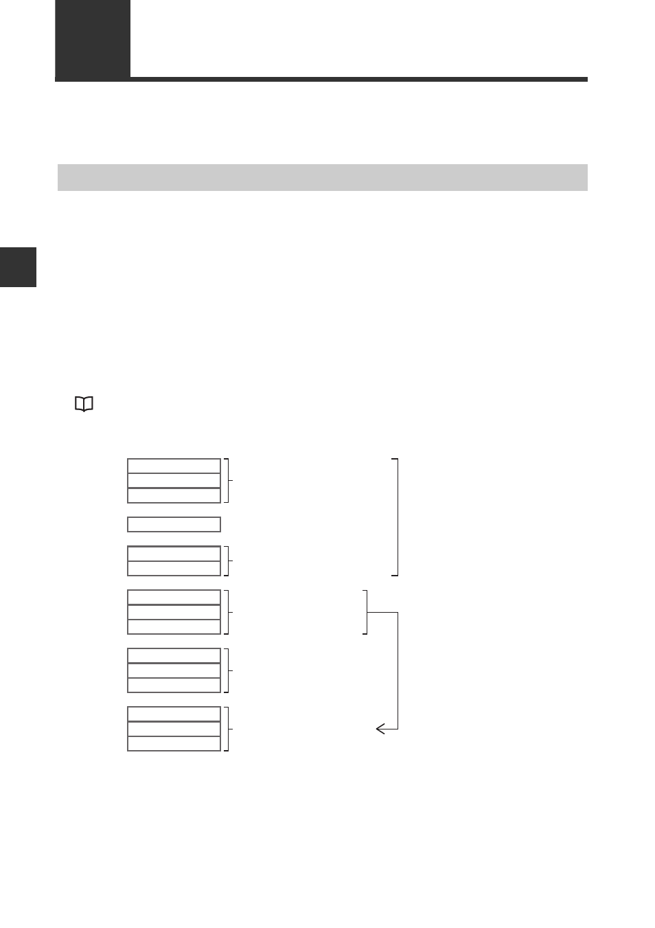
The frame length of the DL-PD1 slave diagnosis is the maximum of 67 bytes. The slave
diagnosis consists of 6-byte standard diagnosis, 4-byte Identifier-related diagnosis, 9-
byte module status and maximum of 48-byte Channel-related diagnosis. The frame
length of the Channel-related diagnosis changes depending on the number of sensor
amplifiers connected. The minimum length is 3 bytes and the length increases 3 bytes
per sensor amplifier additionally connected.
Also, the diagnostic function can be set to Enable/Disable by slot at the parameter
setting for DL-PD1. When the diagnostic function is set to Disable, the slot information is
deleted from the diagnostic frame.
1
2
3
4
5
6
7
:
10
11
:
19
20
:
67
:
:
:
Octet
Station status 1 to 3
PROFIBUS DP master address
Manufacturer ID
Identifier-related diagnosis
(Error information)
Module status
Channel-related diagnosis
Minimum 3 bytes
3 bytes increase per slot
Standard Diagnosis
Channel-related
Diagnosis