2 installation and connection to sensor amplifiers, Mounting and connection to sensor amplifiers, Mounting and connection to sensor amplifiers -3 – KEYENCE DL-EP1 User Manual
Page 19: Installation and connection to sensor amplifiers
2-3
2
C
onn
ec
tion
and
C
onf
ig
ur
at
ion
- EtherNet/IP Compatible Network Unit DL-EP1 User’s Manual (FD-MH) -
2-2
Installation and Connection to Sensor Amplifiers
Number of Connectable Sensor Amplifiers
* Cannot be connected to a panel mounting type.
This section describes how to mount the DL-EP1 on the DIN rail and to connect it to
sensor amplifiers.
Sensor amplifiers supporting D-bus are connectable. You can connect one sensor to
the DL-EP1 as a main unit and one or more sensors to the main unit as expansion
units. (D-bus is the name of KEYENCE's wiring-saving system for sensor amplifiers.)
If the sensor amplifier is D-bus compatible, different models can be connected
together.
How many and what types of sensor amplifiers can be connected depends on the
sensor amplifiers or units to be connected. Please inquire for details.
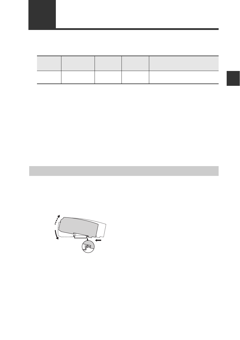
Mounting the DL-EP1 on the DIN rail
1
Align the claw on the bottom of the DL-EP1 with the DIN rail. While
pushing the amplifier in the direction of arrow (1), press down in the
direction of arrow (2).
2
To remove the DL-EP1, raise the amplifier in the direction of arrow (3)
while pushing the DL-EP1 in the direction of arrow (1).
Name
Amplifier
form
Main unit
Expansion
unit
Maximum number of
connectable units
FD-MH
Series*
DIN rail mount
type
FD-MA1A
FD-MA1AP
FD-MA2A
FD-MA2AP
10
(1 main unit, 9 expansion units)
Mounting and connection to Sensor Amplifiers
(3)
(2)
(1)