Video out sequence screen, Ext switcher screen, Setting menus – Panasonic AG-DTL1P User Manual
Page 49: Menu page p7
Attention! The text in this document has been recognized automatically. To view the original document, you can use the "Original mode".
Setting menus
Menu page P7
[TERMINAL INPUT SELECT!
P7
EXT TIMER IN
OFF
TIME ADJUST IN
9:00
[TERMINAL OUTPUT SELECT!
ALARM/SENSOR OUT
CONTINUE
ERROR WARN/REC OUT
WARNING
EXT TIMER OUT
START 0:00
END 0:00
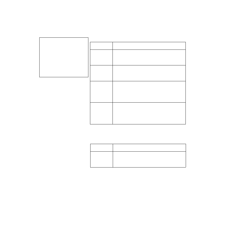
[VIDEO OUT SEQUENCE]
SW INTERVAL
2s
BYPASS CAMERA
OFF
BLACK MATTE
OFF
LL CAMERA
OFF
[EXT SWITCHER]
MODE
VIDEO OUT
VIDEO OUT SEQUENCE screen
Menu item
Description of function
SW INTERVAL
For setting the timing at which the video signals which are supplied
from the camera and which are to be output from the rear panel
VIDEO OUT connector are to be switched.
Is (1 sec.), 1.5s (1.5 sec.), 2s (2 sec.), 2.5s (2.5 sec.), 3s (3 sec.),
4s (4 sec.), 5s (5 sec.), 10s (10 sec.)
BYPASS CAMERA
For setting whether the video signals of a specific camera are not to
be output from the VIDEO OUT connector.
OFF : The video signals of all the cameras are output.
Cl—C16: The video signals of the specified camera/s are not
output.
BLACK MATTE
For setting the processing of the black burst signal when switching
the video signals which are output from the video signal output
connector.
ON : The black burst signal is instantly output when the video signal
is switched.
OFF: The black burst signal is not output when the video signal is
switched.
LL CAMERA
For setting the synchronization system of the connected cameras.
ON : Line-lock type of cameras
OFF: Internal sync and external sync type of cameras
• Use of the internal sync type of cameras is recommended.
• Select the ON setting when even one line-lock type of camera is
used.
The underlining indicates the factory mode setting.
EXT SWITCHER screen
Menu item
Description of function
MODE
For switching the function of the EXT SW INA/IDEO OUT connector
on the rear panel.
VIDEO OUT: The connector is used to outout the video sianals.
EXT SW IN : The connector is used to input the signals of the
external sequential switcher.
The underlining indicates the factory mode setting.
49