Alarm memory recall and power loss memory recall, Notes, Useful functions – Panasonic AG-DTL1P User Manual
Page 26
Attention! The text in this document has been recognized automatically. To view the original document, you can use the "Original mode".
Useful functions
Alarm memory recall and power
loss memory recall
Alarm memory recall is a function for storing in the
memory those dates/times and number of occasions
on which the alarm recording and sensor recording
functions were activated.
Power loss memory recall is a function for storing in
the memory those dates/times and number of
occasions on which the primary power supply was
shut off due to a power outage, etc.
J
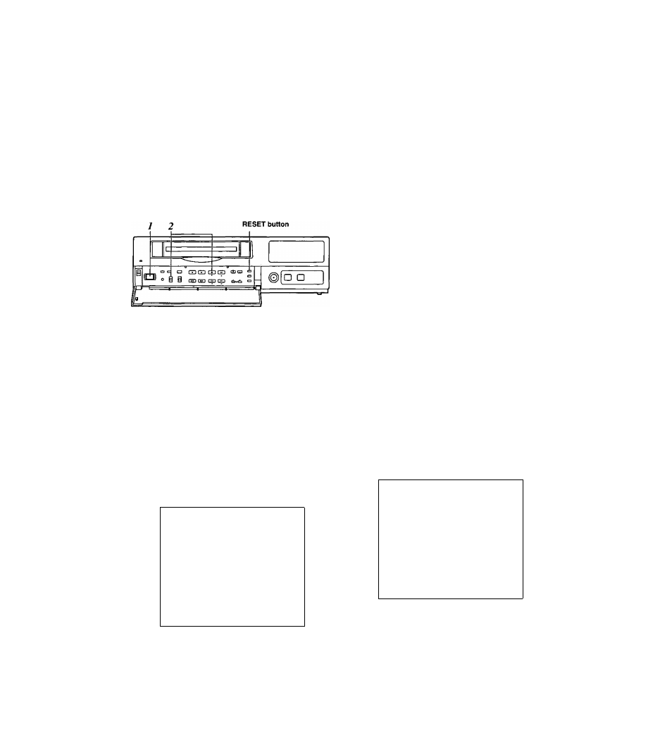
Set the POWER switch to ON.
2
Set the PROGRAM switch to the MENU position
while holding down the STOP button.
The ALARM RECALL screen and POWER LOSS
MEMORY screen now appear.
The alarm number/s and dates/times when the
alarm signal was input are displayed on the
ALARM RECALL screen.
The number of times the primary power source has
been shut off and the dates/times when this
happened are displayed on the POWER LOSS
MEMORY screen.
(Data is displayed in sequence with the latest at
the top of the screen.)
[ALARM RECALL]
29
12 - 30 - 2000
3:15
28
12 - 04 - 2000
12:10
27
10 - 25 - 2000
2:20
26
9 - 10 - 2000
2:30
25
8 - 11 - 2000
6:55
24
5- 10-2000
3:22
23
4 - 11 - 2000
6:55
22
3- 10-2000
3:22
[POWER LOSS MEMORY]
14
12 - 01 -2000
12:00
13
10 - 05 - 2000
10:30
12
08- 10 - 2000
9:20
11
3-02-2000
7:00
The following display appears when alarm recording
was never performed or when the primary power
supply was never shut off.
[ALARM RECALL]
■ + + - 4 ; - f - 4=4;
4^ 4-—4 4—4 4 4 4
4; 4-—4 4—4 4 44
44—44—444 4
44—4 4—4 4 44
4 4:44
4 4:44
4 4:44
4 4:4 :f-
4 4:4 4
4^::41-
4 4:44
4 4:44
[POWER LOSS MEMORY]
44—44—4444
44:44
>f; rf: 44—44—44 44
4 4:4 4
44 4 4"—4 4—4 4 44
4 : 4 4
• Data for up to 8 alarms is stored on the ALARM
RECALL screen whereas data for up to 4 power
losses is stored on the POWER LOSS MEMORY
screen.
• A total of 99 alarms and 99 power tosses are stored
in the memory.
When 99 is exceeded, the count returns to “00.”
• As with alarm recordings, the sensor recordings are
stored as alarm memory data.
• The alarm memory data and power loss memory
data are stored in the memory circuit inside the unit.
They are not recorded on the tape.
• When the PROGRAM switch is set to any position
except MENU, the ALARM RECALL screen and
POWER LOSS MEMORY screen displays are
cleared.
• When the RESET button is pressed while the
ALARM RECALL screen is displayed, the memory
can be cleared, but the POWER LOSS MEMORY
screen is not cleared.
[ALARM RECALL]
44 44_44_4444
44:4 4
4 4 4 4—4 4—4 4 4 4
'f’^ ^ ^ ^
44:44
44 44—44—4444
44 4>f:_4:ir_4444
4.-(^:4 4
44 44-44-4444
4 4;;(;4
[POWER LOSS MEMORY]
14 12-01-2000
12:00
13 10-05-2000
10:30
12 08-10 - 2000
9:20
11 3 - 02 - 2000
7:00
26