Dynon Avionics SkyView System Installation Guide User Manual
Page 264
SV-ADSB-470 Installation, Configuration, and Testing
14-4
SkyView System Installation Guide - Revision S
sources of these products. You may also find it helpful to own a pin insertion/extraction tool as
well.
Additional harness construction and wiring information can be found in Appendix C: Wiring and
Electrical Connections.
The SV-ADSB-470 has a single D9 female connector which provides the data and power inputs
to the module. A single BNC connector attaches to the antenna.
SV-ADSB-470 Interface – Pinout (Female D9 on module / Male D9 on harness)
Pin
Function
Notes
1
10-30V DC
Connect to Aircraft Power
2
SV-ADSB-470 Serial RX
Data Input from SkyView
3
SV-ADSB-470 Serial TX
Data Output to SkyView
4
Ground
Connect to Aircraft Ground
5
No Connect
-
6
No Connect
-
7
No Connect
-
8
No Connect
-
9
No Connect
-
Table 51 – SV-ADSB-470 Female D9 Pinout
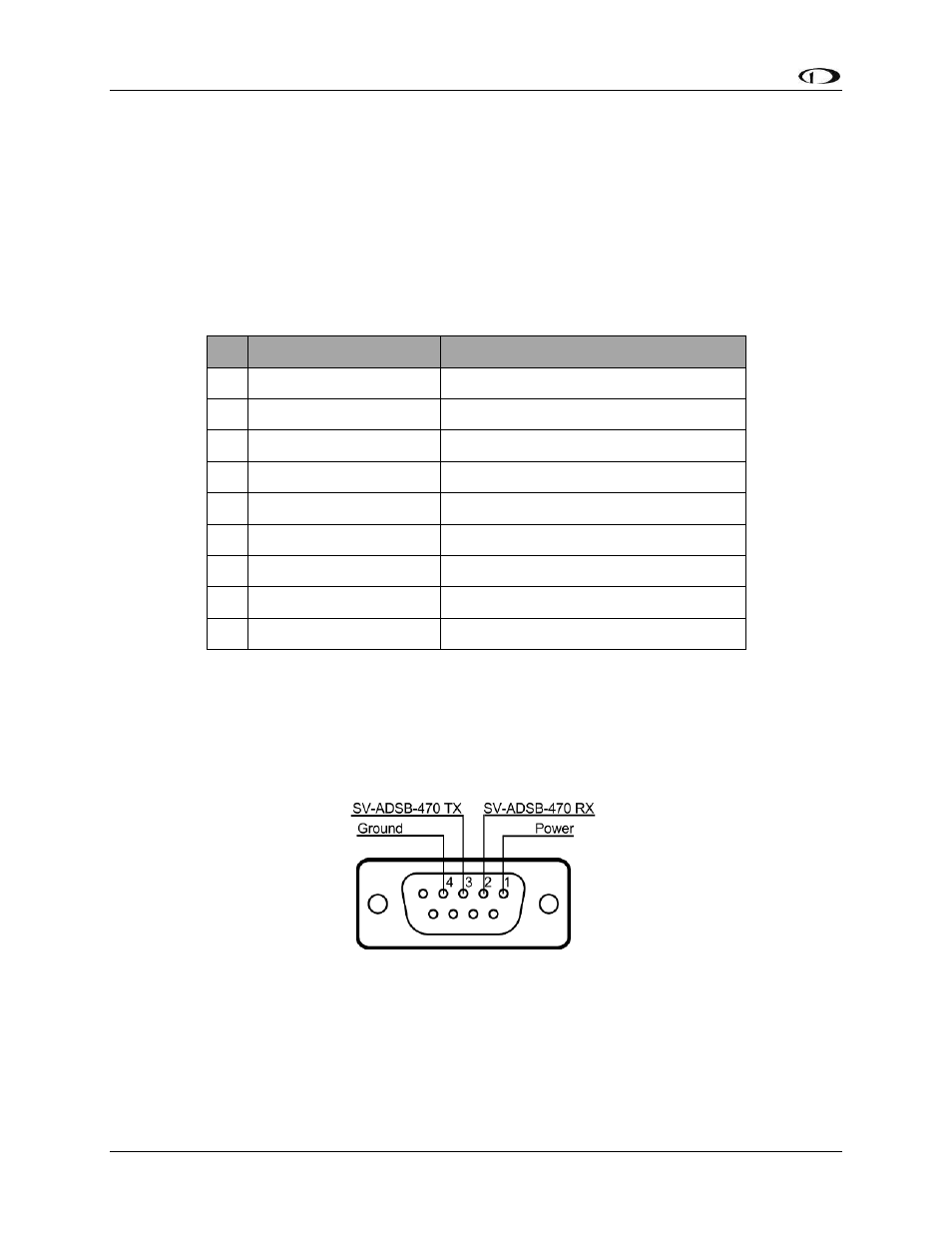
The pin out depicted in Figure 92 below depicts the view from the rear of your male D9
connector – the view you will have of your harness connector as you are inserting pins into the
harness. Note that the pin numbers are labelled on the face of both the female and male
connector.
Figure 92 – SV-ADSB-470 connector diagram (from back side of male D9 connector on the wiring harness)
The following table shows the connections for each of SkyView’s nominally available serial ports
(serial port 5 is usually used for connection to the SV-GPS-250 module). Only ONE of the
following serial ports will be used: