B&C Technologies DI-325 Industrial User Manual
Page 36
OPERATING AND PROGRAMMING INSTRUCTIONS
8-5
Address:
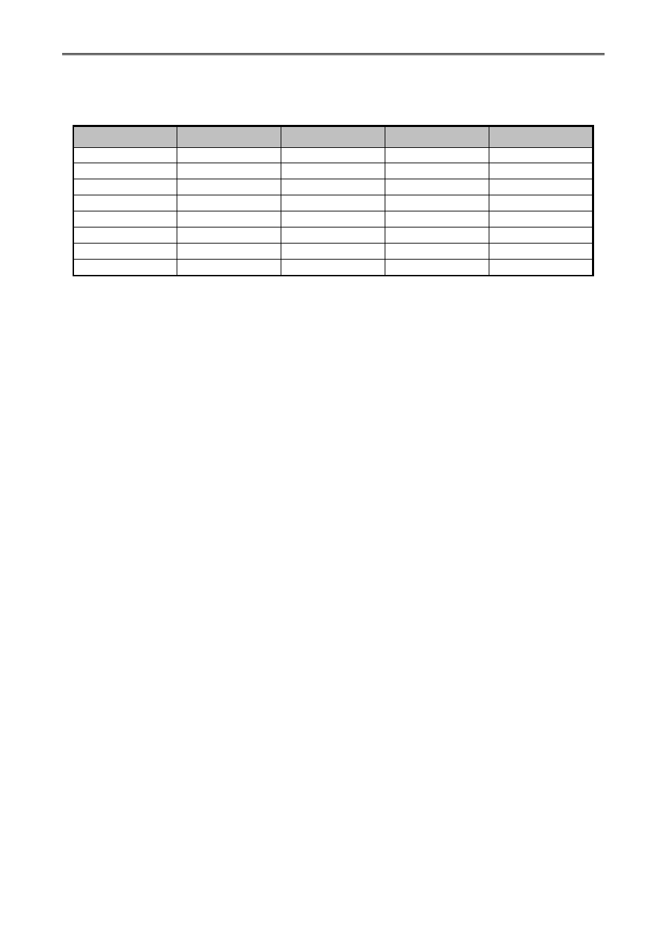
Every extension board connected to a controller must have a unique address. This address
may vary between 1 and 8. The address can be set-up with the dipswitches on the extension board:
Switch 1
Switch 2
Switch 3
Switch 4
Address
OFF OFF OFF OFF 1
ON OFF OFF OFF 2
OFF ON OFF OFF 3
ON ON OFF OFF 4
OFF OFF ON OFF 5
ON OFF ON OFF 6
OFF ON ON OFF 7
ON ON ON OFF 8
2.3 I/O signals from and to the dryer
By default, the inputs and outputs on the dryer controller board have a fixed assignment.
Depending on the type of the machine, the assignment of the inputs and outputs on the extension
boards may vary. In this chapter the assignments and purpose of the inputs and outputs on the CPU
board are described.
2.3.1 Input signals on the CPU board
As described in chapter 2.1, the dryer CPU board has 16 digital inputs available to connect
signals needed to control the dryer.
In the input list below reference is made to message numbers which will be displayed when
an input is not in the right state. Full details of the list of messages with corresponding numbers can
be found in chapter 7.
Input 1: Door closed
This input should be ‘on’ when the door is closed. A program can only be started if the door
is closed. If a dryer is on a drying cycle or cool-down cycle when the door is opened the cycle will
stop and message 13 will be displayed. If a cycle is finished (after drying and cooling-down) and
the door is opened the controller will be ready for a new cycle.
Input 2: Filter door open
This input should be on’ if the filter door or drawer is closed. If the filter door or drawer is
opened, message 12 will be displayed. If the dryer was in a drying, cool-down or anti-crease cycle,
this cycle will be stopped. After closing the filter door or drawer again, the cycle may be restarted
with the start button on the panel.
Input 3: Air flow switch
To detect if the blower creates sufficient air flow an air flow switch is available. This air
flow switch should be in the ‘off’ position when the dryer blower is off. When the blower starts, the
air flow switch should go to the ‘on’ position after the blower has created sufficient air flow. At the
moment the dryer is started, the control checks if the air flow switch is in the ‘off’ position. If not,
message 14 will be displayed. After the blower has been started, the air flow switch must go to the
‘on’ position within an adjustable delay (machine parameter 33, see chapter ‘Machine parameters’).
If the air flow switch isn’t in the on position in time, the dryer will be stopped again and message 14
will be displayed. Because of fan momentum, the air flow switch will not be in the ‘off’ position
directly after the output for the blower is stopped. This means that if the stop button is pushed and