B&C Technologies DI-325 Industrial User Manual
Page 18
INSTALLATION PROCEDURES
3-9
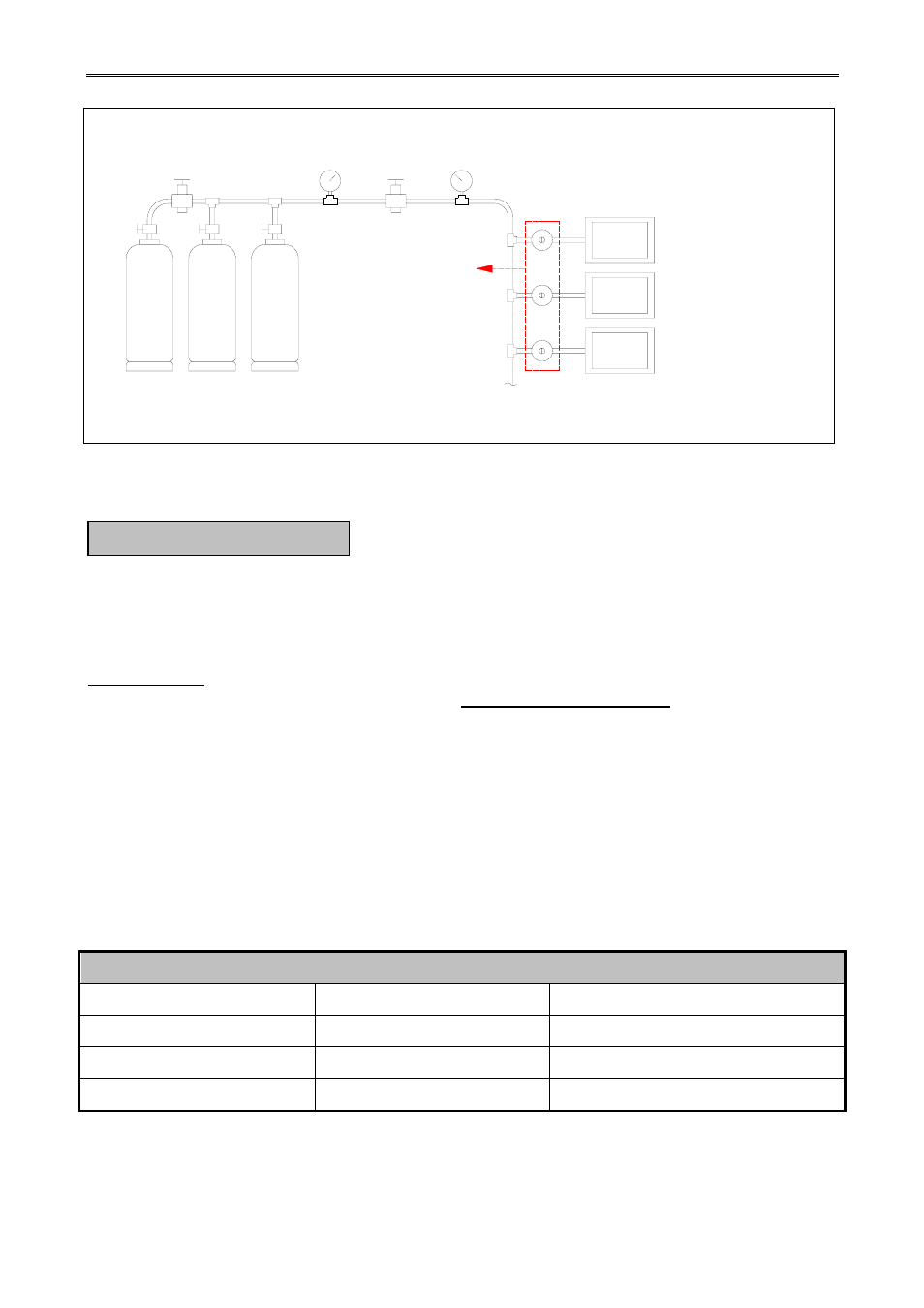
Figure.3-3 Typical of Gas Installation
It is your responsibility to have all steam plumbing connections made by a qualified
professional to assure that the installation is adequate and conforms to local and state regulations or
codes.
IMPORTANT: Failure to comply with the requirements stipulated in the manual can result in
component failures, which will VOID THE WARRANTY.
NOTE:
The dryer model 325 lbs is manufactured with a pneumatic (piston) damper
system, which requires an external supply of air (80 psi ± 10 psi). See Steam
Damper Air System Connections.
1.
Steam Requirements, High Pressure
a.
Inlet ------ 2 inches supply line connection.
b.
Return --- 2 inches return line connection.
Table 3-3 Steam Requirements High Pressure
Operating Steam Pressure, High Pressure
Maximum
125 Psig
8.79 kg. / sq. cm.
Minimum
100 Psig
7.03 kg. / sq. cm.
Heat Input (Normal Load)
35 Bhp
35 Bhp
Consumption (Approximate)
1,125 lbs / hr
511.4 kg. / hr
H. STEAM INFORMATION
MAIN GAS SUPPLY TANKS
HIGH PRESSURE 0-300PSI
PRESSURE
RELIEF VALVE
HIGH PRESSURE
GAUGE 0-300PSI
PRESSURE GAUGE 0-60PSI
MEASURING 7PSI (0.48BAR)
HIGH PRESSURE
REGULATOR
GAS SUPPLY LINE 7PSI
LOW PRESSURE
SECOND STAGE
GAS REGULATOR
MAX INLET PRESSURE
10PSI (0.69BAR)
OUTLET PRESSURE
12-14 INCHES WC. (LPG)
4.5-14 INCHES WC. (NG)
GAS DRYER MACHINE
WITH GAS VALVE MAX INLET
PRESSURE 0.5PSI BUT IF USE
SECOND STAGE REGULATOR
WITH 11 INCHER WC. 0.41PSI (LPG)
4 INCHES WC.0.145 PSI (NG)