B&C Technologies DI-325 Industrial User Manual
Page 16
INSTALLATION PROCEDURES
3-7
NOTE:
Undersized gas piping will result in ignition problems, slow drying, increased use
of energy, and can create a safety hazard.
The dryer must be connected to the type of heat/ gas indicated on the dryer data label
affixed to the back of the dryer at the upper right hand comer. If this information does not agree
with the type of gas available, do not operate the dryer. Contact the distributor who sold the dryer or
the factory.
IMPORTANT: Any burner changes or conversions must be made by a qualified professional.
The input ratings shown on the dryer data label are for elevations of up to 2,000 feet, unless
elevation requirements of over 2,000 feet were specified at the time the dryer order was placed with
the factory. The adjustment or conversion of dryers in the field for elevations over 2,000 feet are
made by changing each burner orifice. If this conversion is necessary, contact the distributor who
sold the dryer or contact the Dryer factory.
2.
Technical Gas Data
a. Gas Specifications
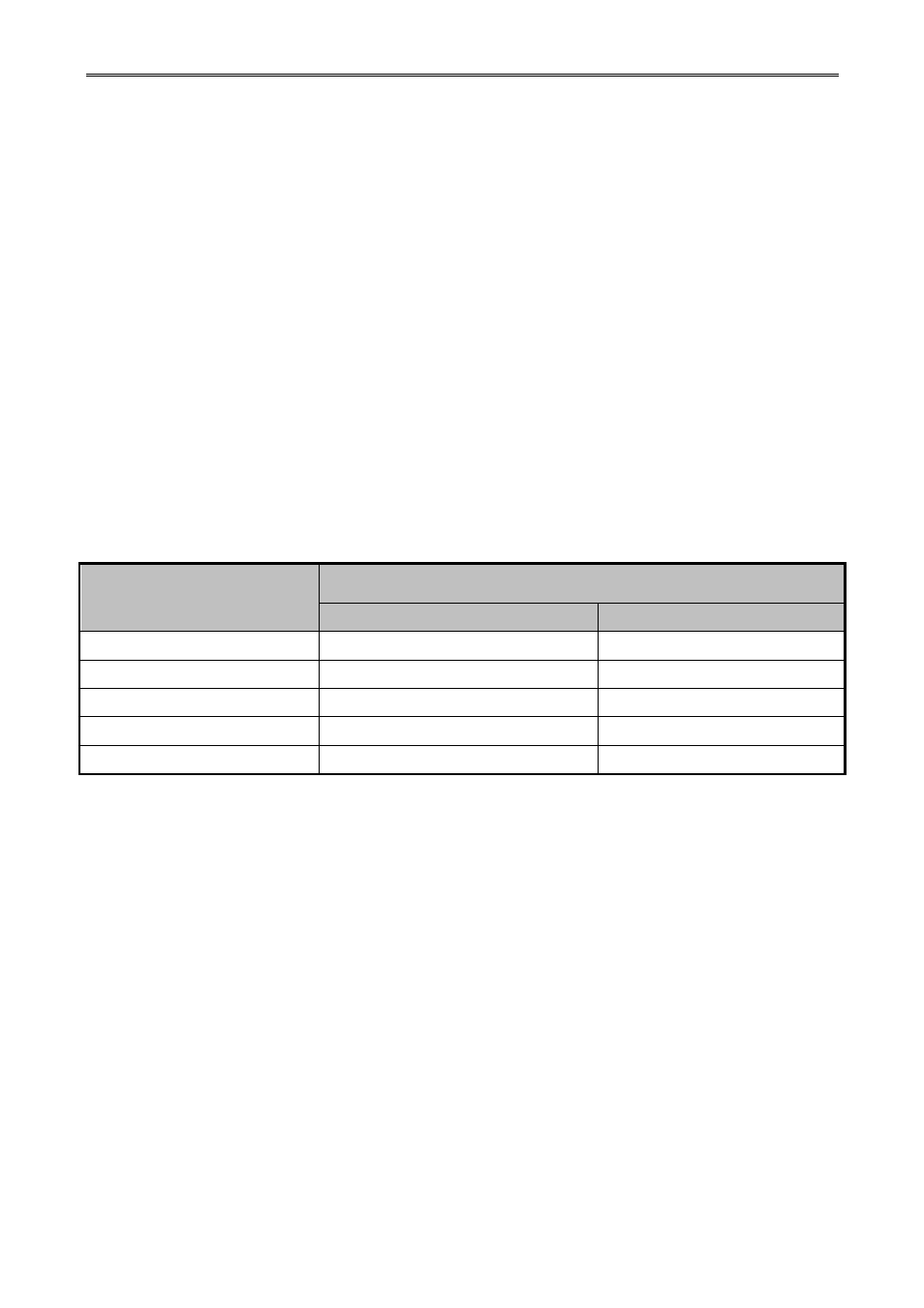
Table 3-2 Technical Gas Data
* Measured at gas valve pressure tap when the gas valve is on.
b. Gas Connections
Inlet supply size ---------- 1.5 inch N.P.T. (minimum)
Inlet connection ---------- 1.25 inch N.P.T.
Btu / hr input (per dryer) ---- 1,180,000 Btu / hr.
1) Natural Gas
Regulation is controlled by the dryer’s gas valve’s internal regulator. Incoming supply
pressure must be consistent between a minimum of 4.5 inches and a maximum of 14.0 inches water
column pressure.
2) Liquid Propane (L.P.) Gas
Dryers made for use with L.P. gas have the gas valve's internal pressure regulator blocked
open so that the gas pressure must be regulated upstream of the dryer. The pressure measured at
each gas valve pressure tap must be a consistent 11.0 inches water column. There is no regulator or
Description
Type of Gas
Natural (NG)
Liquid Propane (LPG)
Manifold Pressure
3.5 – 4.0 inches H
2
O.
10.5 – 11.0 inches H
2
O.
Inline Pressure
4.5 – 14.0 inches H
2
O.
12.0 – 14.0 inches H
2
O.
Drill Nozzle Size (Hole)
4 mm.
3 mm.
Inlet supply size (Minimum) 1.5
inches
1.5inches
Inlet connection
1.25 inches
1.25 inches