B&C Technologies DI-325 Industrial User Manual
Page 20
INSTALLATION PROCEDURES
3-11
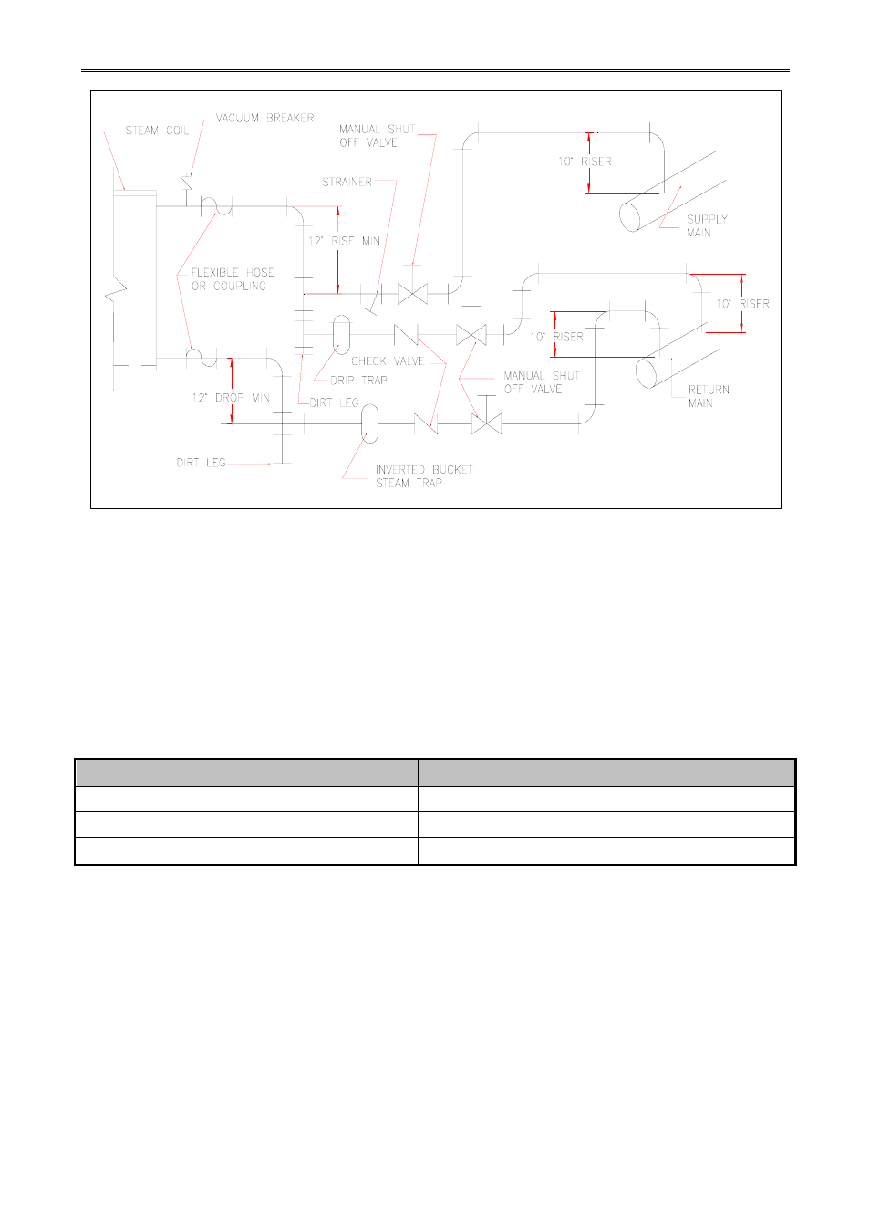
Figure.3-4 Steam Damper System
3.
Steam Damper Air System Connections
The dryer model 325 lbs is manufactured with a pneumatic (piston) damper system, which
requires an external supply of compressed air. The air connection is made to the steam damper
solenoid valve which is located on the outer top, at the rear left hand corner of the dryer.
a.
Air Requirements
Table 3-4 Air Requirements
Compressed Air Supply
Air Pressure
Normal 80
psi
Minimum Supply
70 psi
Maximum Supply
90 psi