B&C Technologies DI-325 Industrial User Manual
Page 33
OPERATING AND PROGRAMMING INSTRUCTIONS
8-2
2. Connecting the controller and the extension boards
A dryer controller set always comprises a dryer controller CPU board, with inputs and
outputs on board. Optionally, the controller can be expanded with extension boards to increase the
number of available inputs and outputs. All print boards have to be connected to a power supply and
to the inputs and outputs through the available connectors. This chapter describes the location and
the purpose of each available connector on the print boards.
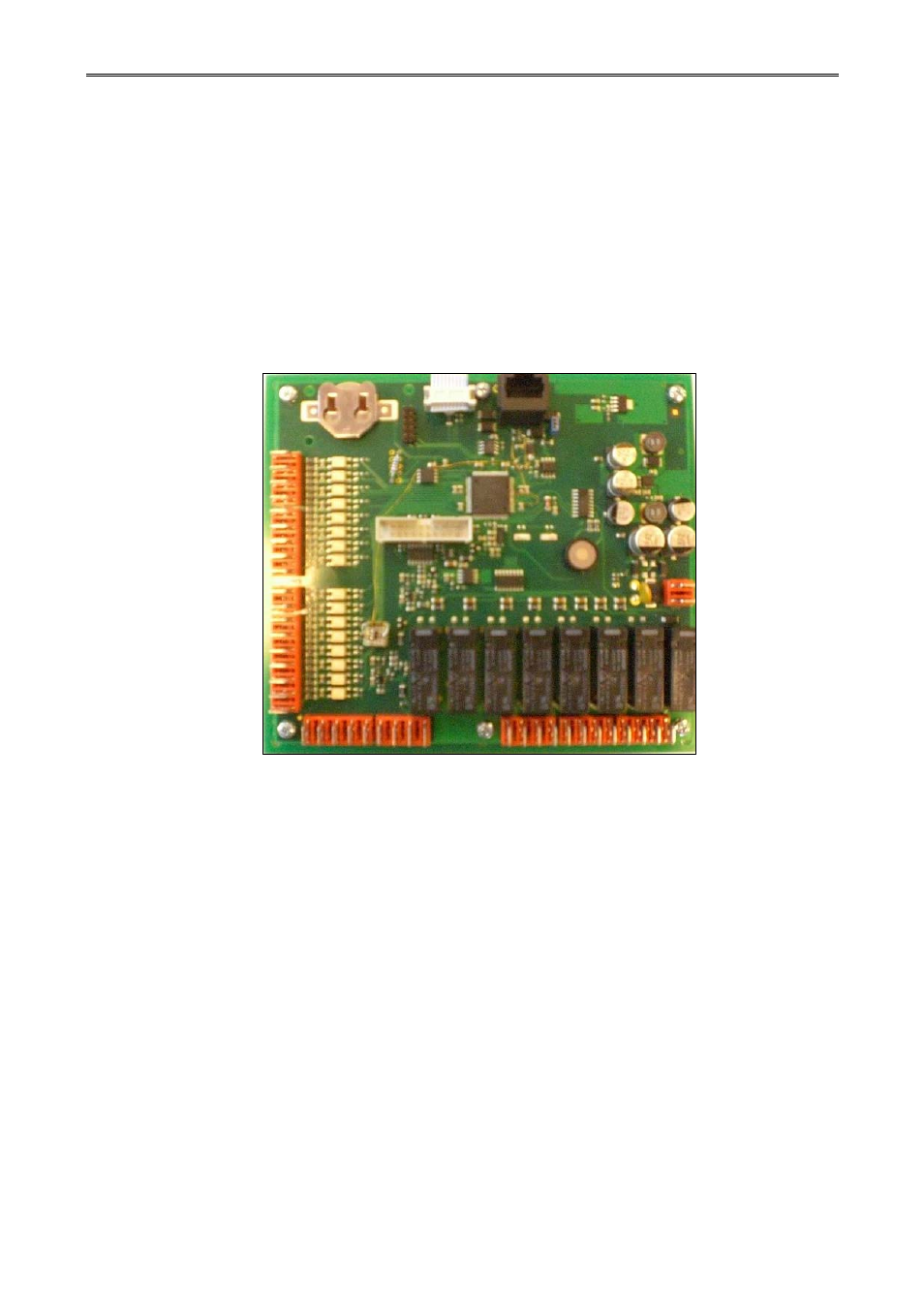
2.1 Dryer controller DQ 01
The dryer controller is build up from 2 print boards, a processor board and a front-print
board. The processor board has number M721A and the front-print board with the buttons and the
displays, has number M721B. All the connections on the dryer controller are on the rear of the
processor board. The connectors are used for different purposes:
2.1 Battery
J7: Inp
uts 1 to 8
Pin 1:
Input 1
Pin 2:
Input 2
Pin 3:
Input 3
Pin 4:
Input 4
Pin 5:
Input 5
Pin 6:
Input 6
Pin 7:
Input 7
Pin 8:
Input 8
Pin 9:
Common for inputs 1 until 8 (0VDC or 24VAC neutral)
J8: Power supply (21-24 VAC/VDC)
Pin 1:
24VDC / 24VAC
Pin 2:
0VDC / 24VAC Neutral
9
9
1
1
J7
J8
J10
J11
J9
1
9
1
12
1
2