Install latch and strike, Remove cover and battery case – Weiser SmartCode5 - Traditional & Contemporary User Manual
Page 2
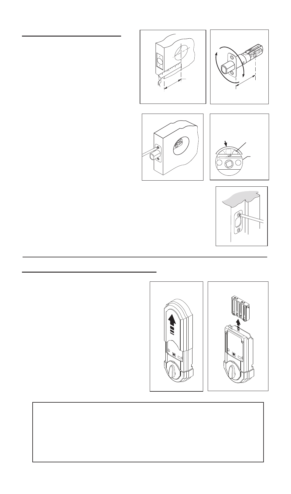
2-3/8"
(60mm)
or
2-3/4"
(70mm)
1-1/2
(38mm)
hole
2-3/4" (70mm)
1. Install latch and Strike.
Fig. 3
Fig. 1
d. Leave the bolt in the extended position.
e. Install strike with two 1-1/2” (38mm) wood screws
(see figure 5).
2. Remove cover and battery case.
2
Area
Crank
a. Determine your backset, see
figure 1.
b. If a 2-3/4” (70mm) backset is
required, extend bolt and adjust
latch as shown. (See figure 2).
Fig. 2
Fig. 5
Fig. 4
c. Install latch, securing with small
wood screws (see figure 3). Note:
For a 1-1/2” (38mm) diameter
hole, test if latch extends and
retracts smoothly. Area indicated
may require addition clearance for
crank of latch to function properly
(see figure 4).
a. Remove cover from assem-
bly by sliding cover up and off,
see figure. 6
b. Remove the battery case
from interior assembly by lift-
ing the case up and out and
set aside, see figure 7.
Fig. 7
Fig. 6
Important before proceeding:
1. Verify that position #2 of the “Settings Switch” is in the OFF posi-
tion. (Refer to section 10.)
2. Work with the door open (away from jamb) to avoid accidental
lock out.
3. Make sure the bolt is in the extended (locked) position.