3 load cells, Load cells, Figure 2-2). f – Rice Lake 920i USB Installation Manual V5.05 User Manual
Page 16
10
920i Installation Manual
•
For cables with braided shielding, strip cable
insulation and braided shield from a point just
past the grounding clamp. Strip another half inch
(15 mm) of insulation only to expose the braid
where the cable passes through the clamp (see
Figure 2-2).
Cord Grip
Insulated
cable
Foil
(silver side out)
Grounding clamp
Shield wire
(cut)
Length of foil before folding
back on cable insulation
Cut insulation here
for foil-shielded cables
Braid
Cut insulation here
for braided cables
NOTE: Install lockwashers
first, against enclosure,
under grounding clamp
Figure 2-2. Grounding Clamp Attachment for Foil-Shielded
and Braided Cabling
•
For load cell cables, cut the shield wire just past
the grounding clamp. Shield wire function is
provided by contact between the cable shield and
the grounding clamp.
•
Route stripped cables through cord grips and
clamps. Ensure shields contact grounding clamps
as shown in Figure 2-2. Tighten grounding clamp
nuts.
•
Finish installation using cable ties to secure
cables inside of indicator enclosure.
2.3.3
Load Cells
To attach cable from a load cell or junction box to an
installed A/D card, route the cable through the cord
grip and ground the shield wire as described in
Section 2.3.2 on page 9.
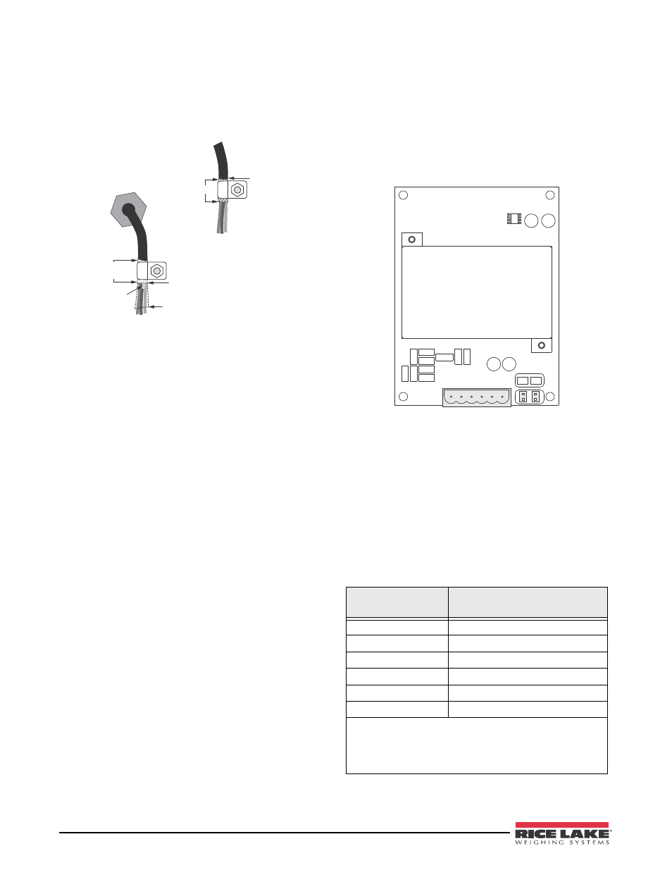
Next, remove connector J1 from the A/D card. The
connector plugs into a header on the A/D card (see
Figure 2-3). Wire the load cell cable from the load cell
or junction box to connector J1 as shown in Table 2-1.
SIG+
SIG–
SEN+
SEN–
EXC+
EXC–
J1
JP2
JP1
Figure 2-3. Single-Channel A/D Card
If using 6-wire load cell cable (with sense wires),
remove jumpers JP1 and JP2 before reinstalling
connector J1. For 4-wire installation, leave jumpers
JP1 and JP2 on. For 6-wire load cell connections on
dual-channel A/D cards, remove jumpers JP3 and JP4
for connections to J2.
When connections are complete, reinstall load cell
connector on the A/D card and use two cable ties to
secure the load cell cable to the inside of the enclosure.
Table 2-1. A/D Card Pin Assignments
A/D Card
Connector Pin
Function
1
+SIG
2
–SIG
3
+SENSE
4
–SENSE
5
+EXC
6
–EXC
•
For 6-wire load cell connections to connector J1, remove
jumpers JP1 and JP2.
•
For 6-wire load cell connections to connector J2 (dual A/D
cards), remove jumpers JP3 and JP4.