8 data formats, Character is – Rice Lake 920i USB Installation Manual V5.05 User Manual
Page 129
Appendix
123
11.8
Data Formats
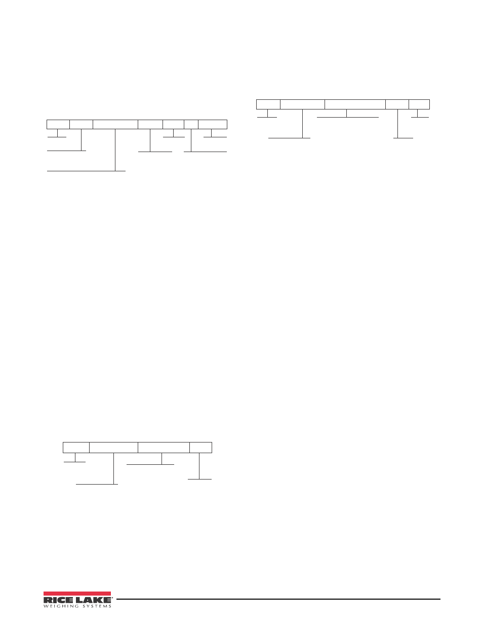
Continuous Output Serial Data Format
If continuous transmission is configured for a serial
port (STREAM parameter set to LFT or INDUST on
the SERIAL menu), the 920i sends data using the
Consolidated Controls serial data format shown in
Figure 11-2:
ASCII 02
decimal
Polarity:
<space> = Positive
<–> = Negative
Weight: 7 digits, right-justified, dummy
zeroes, decimal point with no leading
zeroes except for leading zero immediately
preceding the decimal point. Leading
zeroes transmitted as spaces.
L = pounds
K = kilograms
T = tons
G = grains
O = ounces
G = Gross
N = Net
Status:
<space> = valid
I = Invalid
M = Motion
O = Over/under range
Z = Center of zero
or
Figure 11-2. Continuous Output Serial Data Format
Demand Output Serial Data Format
When demand mode is configured for the serial port
(STREAM parameter set to OFF), the 920i uses a data
string formatted for a basic ticket printout. The
particular ticket format printed depends on the
indicator configuration.
You can customize the ticket to work with a wide
variety of printers, scoreboard displays, and other
remote equipment. See Section 7.0 on page 67 for
more information on custom print formats.
RS-485 Data Formats
Two-wire RS-485 communications is available on port
4 of the CPU board; four-wire RS-485 communications
is supported on the “A” ports of any installed serial
expansion cards.
The 920i has a built-in RS-485 software protocol
which is enabled when you assign a non-zero address
to the indicator. Valid RS-485 addresses must be in the
range 1–255; the address is specified on the ADDRESS
parameter on the SERIAL menu.
All remote commands are initiated using the data
format shown in Figure 11-3:
ASCII 02
decimal
Address of the
receiving indicator
EDP serial command
NOTE: Host must send
renders all indicators unable to
respond to serial commands.
ASCII
13 decimal
Figure 11-3. RS-485 Send Data Format
If the initiating device address matches the port address
of an 920i on the RS-485 network, that indicator
responds. For example, with demand outputs, or in
response to an XG#1 command, the responding
indicator uses the format shown in Figure 11-4:
ASCII 02
decimal
Address of the
transmitting indicator
Response commands from
indicator:
<first line>
<additional lines>
<last line>
where EOL =
(set by TERMIN parameter on the
SERIAL menu)
ASCII 13
decimal
ASCII 03
decimal
Figure 11-4. RS-485 Respond Data Format
Example:
To send the XG#1 command from an ASCII
terminal to an indicator at address 65 (decimal) on the
RS-485 network, use the format shown in Figure 11-3.
•
The keyboard equivalent for the start-of-text
(
STX
) character is
CONTROL-B
.
•
The indicator address (65) is represented by an
upper case “A”.
•
The carriage return (CR) character is generated
by pressing the
ENTER
key.
Therefore, to send the XG#1 command to the indicator
at address 65, enter the following at the terminal:
The indicator responds with the format shown in
Figure 11-4: